PAPER DEEP DIVE
Adaptive Whole-Body MPC with Optimal Posture Planning for Humanoid Robots under Unknown Payloads
When a humanoid lifts an unknown payload, abrupt changes in mass, center of mass, and inertia destabilize whole-body control. The paper couples centroidal MPC, adaptive fuzzy balance compensation driven by capture-point error, and triple-integrator posture-transition planning. MPC produces motion references under contact, friction, and joint constraints; fuzzy compensation allocates corrective torques to stance legs; and the planner generates smooth, feasible sit-to-stand and stand-to-sit trajectories. MuJoCo simulation and a 28-DoF humanoid validate stable lifting with 7 kg and 10 kg payloads and robust 7 kg load-carrying during walking.
Adaptive Whole-Body MPC with Optimal Posture Planning for Humanoid Robots under Unknown Payloads
Authors: Manh Cuong Nguyen, Duc Cuong Vu, Viet Anh Vu, Duc Tuan Pham, Toan Nguyen, Minh Hiep Phung, Ngo Anh Vien, Minh Nhat Vu · arXiv: 2601.12972 · Paper · Official code: not released · Related dependency: OCS2
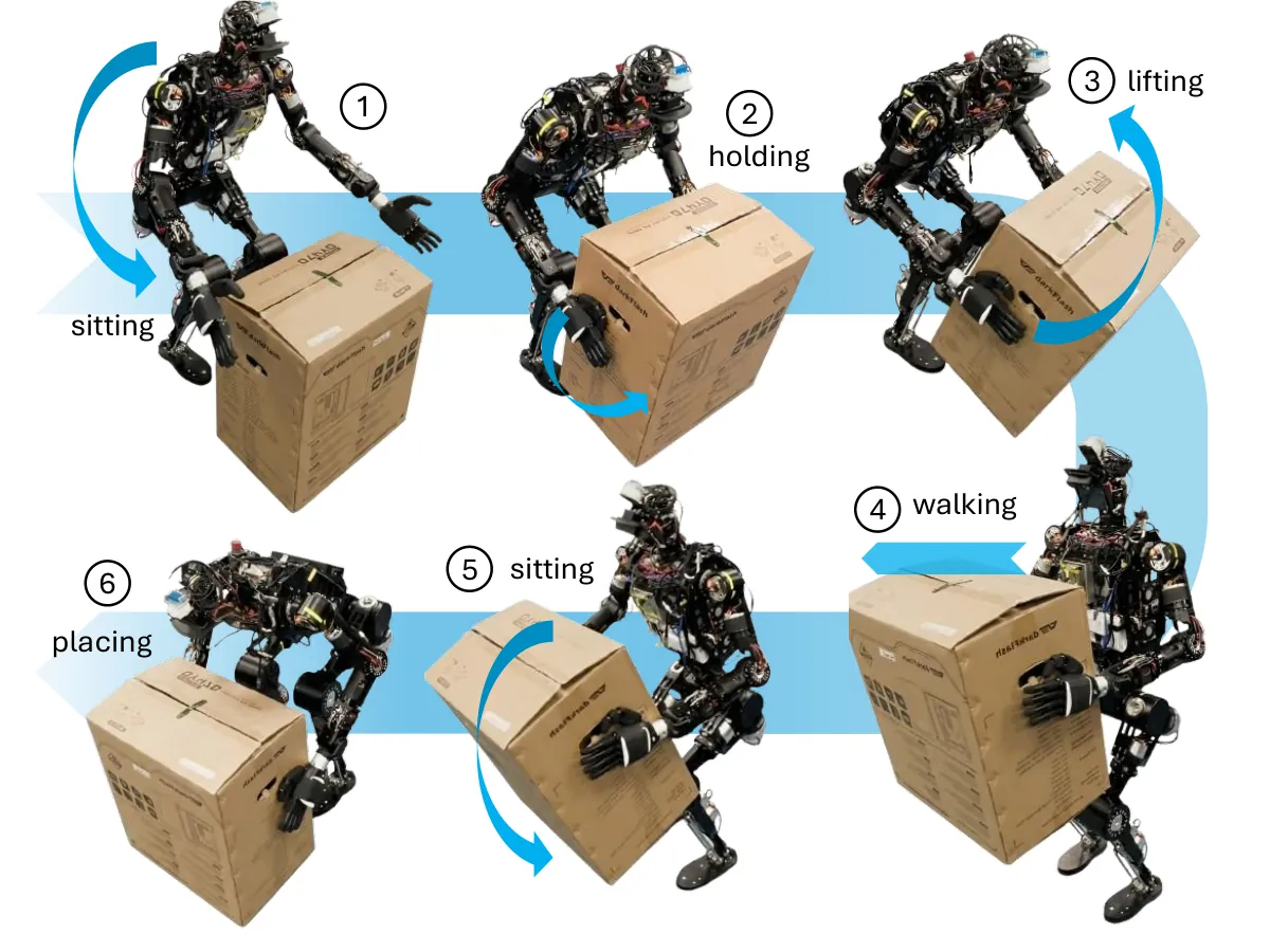
Figure 1: The task spans sitting, grasping, holding, lifting, walking, and placing. Fuzzy compensation constrains center-of-mass drift across all stages.
One-Sentence Summary
Instead of identifying the payload first, the paper lets a centroidal MPC produce constrained nominal motion, an adaptive fuzzy balance controller consume capture-point error to cancel model mismatch, and a triple-integrator posture planner generate feasible squat and transfer trajectories for a real humanoid.
Why This Problem Is Hard
Humanoid material handling looks deceptively simple until the object changes. A robot must approach a package, lower its pelvis, grasp it, stand up, carry it, and put it down. Each transition changes the floating-base dynamics and the contact configuration. In industry, mass, shape, and inertia are often unknown, so a controller tuned for a nominal object can become wrong at the exact instant of grasping.
The difficulty is coupled. Added mass changes the mass matrix. The package moves the center of mass and changes rotational inertia. Contact forces shift between the feet. If the balance controller waits for a tracking error to grow, the center-of-mass projection may already be close to the support boundary. High-gain feedback can then excite oscillations rather than restore stability.
Posture transitions add a second failure mode. Squatting is not a sequence of fixed waypoints for the pelvis. Hip, knee, and ankle angles must remain inside joint limits, the feet must remain feasible contacts, and the pelvis height and pitch determine what horizontal position is kinematically attainable. A reference that looks smooth in configuration space can still be dynamically useless if the center of mass leaves the support polygon.
Prior MPC systems are strong at locomotion under explicit constraints, but many assume known loads. Fuzzy controllers can map uncertain, nonlinear effects into bounded corrections, but by themselves usually lack systematic constraint handling. This paper keeps that boundary: the predictive layer retains contact and state constraints; the fuzzy layer adds a residual torque; the planner ensures that the posture transition is feasible before the robot tries to execute it.
The authors also make a hardware argument. Their robot runs centroidal MPC at 50 Hz, adaptive balance control at 500 Hz, and low-level torque control above 1 kHz. With that timing budget, they cannot fold payload identification, trajectory generation, contact feasibility, and joint tracking into one black-box optimizer. The architecture is therefore explicitly layered.
From Full Dynamics to a Centroidal Planner
The robot is represented by a floating base and actuated joints:
$$\mathbf{q}=[\mathbf{q}_{b}^{\top},\mathbf{q}_{j}^{\top}]^{\top},\qquad \mathbf{q}_{b}\in SE(3),\quad \mathbf{q}_{j}\in\mathbb{R}^{n_j}.$$
With active contacts, the constrained rigid-body dynamics become
$$\mathbf{H}_{bb}(\mathbf{q})\ddot{\mathbf{q}}_{b}+\mathbf{H}_{bj}(\mathbf{q})\ddot{\mathbf{q}}_{j}+\mathbf{n}_{b}(\mathbf{q},\dot{\mathbf{q}})=\mathbf{J}_{cb}^{\top}(\mathbf{q})\boldsymbol{\lambda},$$
$$\mathbf{H}_{jb}(\mathbf{q})\ddot{\mathbf{q}}_{b}+\mathbf{H}_{jj}(\mathbf{q})\ddot{\mathbf{q}}_{j}+\mathbf{n}_{j}(\mathbf{q},\dot{\mathbf{q}})=\boldsymbol{\tau}_{j}+\mathbf{J}_{cj}^{\top}(\mathbf{q})\boldsymbol{\lambda},$$
$$\mathbf{J}_{i}(\mathbf{q})\ddot{\mathbf{q}}+\dot{\mathbf{J}}_{i}(\mathbf{q},\dot{\mathbf{q}})\dot{\mathbf{q}}=0,\qquad \forall i\in\mathcal{C}.$$
The mass matrix is split by floating-base and joint blocks. The terms $\mathbf{n}_b$ and $\mathbf{n}_j$ combine gravity, Coriolis, and centrifugal effects. The wrench $\boldsymbol{\lambda}$ acts through the contact Jacobian. The last equation is the contact constraint: for every active contact $i$, the contact Jacobian forces its acceleration to zero.
The planner then uses centroidal dynamics. If $\mathbf{h}=[\mathbf{h}_l^{\top},\mathbf{h}_a^{\top}]^{\top}$ is linear and angular momentum about the center of mass, then
$$\dot{\mathbf{h}}=\begin{bmatrix}\sum_{i\in\mathcal{C}}\mathbf{F}_{i}+m\mathbf{g}\\ \sum_{i\in\mathcal{C}}\left(\mathbf{r}_{i}\times\mathbf{F}_{i}+\mathbf{M}_{i}\right)\end{bmatrix}.$$
Here $\mathbf{F}_i$ and $\mathbf{M}_i$ are the force and moment at contact $i$, $\mathbf{r}_i$ points from the center of mass to that contact, $m$ is total mass, and $\mathbf{g}$ is gravity. Momentum is related to generalized velocity through the centroidal momentum matrix: $\mathbf{h}=\mathbf{A}(\mathbf{q})\dot{\mathbf{q}}$. Choosing $\mathbf{x}=[\mathbf{h}^{\top},\mathbf{q}_b^{\top},\mathbf{q}_j^{\top}]^{\top}$ gives
$$\dot{\mathbf{x}}=\mathbf{f}(\mathbf{x},\mathbf{u}).$$
This reduction does not discard constraints. It separates the slow prediction problem from high-frequency joint tracking, giving the MPC enough time to enforce friction cones, center-of-pressure limits, and joint bounds.
Architecture
flowchart TB
    H[Desired pelvis height and pitch] --> P[Waypoint posture planner]
    P --> R[Smooth joint references]
    W[Joystick and walking mode] --> M[Centroidal MPC]
    R --> M
    M --> C[Contact forces and motion references]
    C --> B[Whole-body controller]
    S[State estimation] --> E[Capture point error]
    E --> F[Fuzzy balance controller]
    F --> A[Torque allocation]
    B --> A
    A --> J[Leg joint torque commands]
    J --> L[Humanoid low level control]
    L --> S
    P --> R2[Support polygon and joint limit checks]
    R2 --> P
Figure 2: The closed loop separates posture feasibility, constrained prediction, residual balance compensation, and low-level torque execution.
Constrained Centroidal MPC
Over horizon $T$, the nonlinear MPC solves
$$\min_{\mathbf{u}(\cdot)}\quad \Phi(\mathbf{x}(T))+\int_{0}^{T}l(\mathbf{x}(\rho),\mathbf{u}(\rho))\,d\rho$$
$$\text{s.t.}\quad \dot{\mathbf{x}}=\mathbf{f}(\mathbf{x},\mathbf{u}),\quad \mathbf{x}(0)=\mathbf{x}_{t},\quad (\mathbf{x},\mathbf{u})\in\mathcal{X}\times\mathcal{U}.$$
The stage and terminal costs are $l$ and $\Phi$. The constraint sets encode stance-foot friction cones, center-of-pressure feasibility, zero stance-foot velocity, prescribed swing-foot normal velocity, and joint position and velocity limits. The important consequence is that the reference motion is already feasible in the current contact mode.
The low level uses inverse dynamics. After solving the MPC, the first input is $\mathbf{u}(0)=[\dot{\mathbf{q}}_j^{*\top},\boldsymbol{\lambda}^{*\top}]^{\top}$. Exponential joint tracking is imposed by choosing
$$\ddot{\mathbf{q}}_{j}^{*}=-K_{p}\mathbf{e}_{j}-K_{d}\dot{\mathbf{e}}_{j},$$
with $\mathbf{e}_j=\mathbf{q}_j-\mathbf{q}_j^*$ and $\dot{\mathbf{e}}_j=\dot{\mathbf{q}}_j-\dot{\mathbf{q}}_j^*$. The floating-base acceleration follows from the base dynamics:
$$\ddot{\mathbf{q}}_{b}^{*}=\mathbf{H}_{bb}^{-1}\left(\mathbf{J}_{cb}^{\top}\boldsymbol{\lambda}^{*}-\mathbf{H}_{bj}\ddot{\mathbf{q}}_{j}^{*}-\mathbf{n}_{b}\right).$$
Substituting both accelerations into the joint equation gives the nominal torque
$$\boldsymbol{\tau}_{j}=\mathbf{H}_{jb}\ddot{\mathbf{q}}_{b}^{*}+\mathbf{H}_{jj}\ddot{\mathbf{q}}_{j}^{*}+\mathbf{n}_{j}-\mathbf{J}_{cj}^{\top}\boldsymbol{\lambda}^{*}.$$
The authors deliberately avoid an additional task-space QP here. Contact feasibility has already been handled by the centroidal MPC, so another optimization would add tuning and latency without addressing the remaining unknown-payload residual.
Fuzzy Residual Compensation
The fuzzy controller does not estimate mass. It measures where the capture point is going relative to the support polygon. Under a linear inverted pendulum assumption,
$$\boldsymbol{\xi}=\mathbf{r}_{\text{com}}+\frac{\dot{\mathbf{r}}_{\text{com}}}{\omega},\qquad \omega=\sqrt{\frac{g}{z_c}},$$
where $\mathbf{r}_{\text{com}}$ is the ground-projected center of mass and $z_c$ is nominal CoM height. With $\mathbf{c}_{\text{supp}}$ the weighted center of stance contacts, the balance error is
$$\mathbf{e}=\boldsymbol{\xi}-\mathbf{c}_{\text{supp}}=\mathbf{r}_{\text{com}}-\mathbf{c}_{\text{supp}}+\frac{\dot{\mathbf{r}}_{\text{com}}}{\omega}.$$
The forward component $e_x$ drives a pitch correction and the lateral component $e_y$ drives a roll correction. An anti-windup integral $\mathbf{e}_{\text{int}}=\int\mathbf{e}\,dt$ is clamped by $\left|\mathbf{e}_{\text{int}}\right|\le e_{\text{int,max}}$.
Each axis uses a four-layer fuzzy system. Fuzzification maps each input to five Gaussian membership functions labeled NB, NS, Z, PS, and PB:
$$\mu_{\ell}(x)=\exp\left(-\frac{(x-c_{\ell})^{2}}{2\sigma_{\ell}^{2}}\right).$$
The rule base has $5\times5\times5=125$ rules per axis. If deviation belongs to $\mathcal{A}_i$, velocity to $\mathcal{B}_j$, and integral state to $\mathcal{C}_k$, the consequent is $y_{ijk}$. Product inference gives the firing strength
$$w_{ijk}=\mu_{\text{dev}}^{(i)}(e)\cdot\mu_{\text{vel}}^{(j)}(\dot{r})\cdot\mu_{\text{int}}^{(k)}(e_{\text{int}}).$$
The consequent combines a PD-like base term and an integral term:
$$y_{ijk}=\text{clip}_{[-1,1]}\left(y_{\text{base}}^{(ij)}+\Delta_{\text{int}}^{(k)}\right).$$
Defuzzification returns a bounded compensation moment:
$$\tau=S\cdot\frac{\sum_{i,j,k}w_{ijk}y_{ijk}}{\sum_{i,j,k}w_{ijk}},\qquad |\tau|\le\tau_{\max}.$$
The authors describe this law as close to a saturated, gain-scheduled PID on capture-point error, but with effective gains changing jointly with error, velocity, and integral state. The rule centers, widths, output scales, and saturation values were hand tuned once and reused in all experiments.
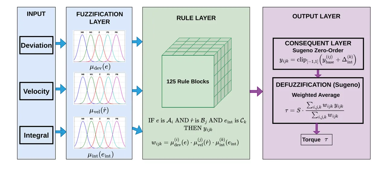
Figure 3: Deviation, CoM velocity, and error integral enter the fuzzy system; bounded pitch and roll compensation leave it.
Torque Allocation to Stance Legs
The task-space compensation $\boldsymbol{\tau}_{\text{comp}}^{\text{task}}=[\tau_{\text{pitch}},\tau_{\text{roll}}]^{\top}$ is allocated only through stance legs. The arms hold the payload, so upper-body corrections would disturb the grasp and change inertia. The allocation minimizes joint torque norm:
$$\boldsymbol{\tau}_{\text{leg}}^{*}=\arg\min_{\boldsymbol{\tau}_{\text{leg}}}\ \boldsymbol{\tau}_{\text{leg}}^{\top}\boldsymbol{\tau}_{\text{leg}}$$
$$\text{s.t.}\quad \Omega(\boldsymbol{\tau}_{\text{leg}})=\boldsymbol{\tau}_{\text{comp}}^{\text{task}}.$$
The map $\Omega$ relates stance-leg joint torques to a task-space moment at the pelvis. This choice keeps the grasp undisturbed and prevents balance error from corrupting swing-leg references. It also bounds the blast radius of the compensator: only joints already supporting the robot participate in correction.
Selecting a Feasible Pelvis Pose
A desired pelvis height and pitch do not uniquely determine posture. Horizontal pelvis position remains free, but only some values yield joints inside limits and a center-of-mass projection inside the support polygon. The paper uses a three-link planar leg with joint vector
$$\mathbf{q}_{w}=[q_{h},q_{k},q_{a}]^{\top}$$
for hip, knee, and ankle. For a candidate pelvis height $h$, pitch $\theta$, and horizontal coordinate $p_x$, inverse kinematics produces $\mathbf{q}_{wr}$. If the solution is outside joint-limit set $\mathcal{Q}$, the algorithm moves $p_x$ by $\operatorname{sign}(\theta)\varepsilon$ within the support polygon until it finds a feasible configuration.
With thigh and shank lengths $l_1$ and $l_2$, and hip-to-ankle distance $d_0$, the closed-form inverse kinematics is
$$q_{k}=\pi-\arccos\left(\frac{l_{1}^{2}+l_{2}^{2}-d_{0}^{2}}{2l_{1}l_{2}}\right),$$
$$q_{h}=\frac{\pi}{2}-\arccos\left(\frac{l_{1}^{2}+d_{0}^{2}-l_{2}^{2}}{2l_{1}d_{0}}\right)-\arctan 2(h,p_{x}),$$
$$q_{a}=-q_{h}-q_{k}-\theta.$$
This abstraction does not model every upper-body degree of freedom. Its purpose is to make a large set of pelvis candidates cheap enough to test during planning.
Figure 4: The hip, knee, and ankle geometry supplies fast feasibility checks for pelvis candidates.
Trajectory Generation as a Jerk-Constrained Optimization
The planner uses a discrete triple integrator rather than direct interpolation. Its state and jerk input are
$$\boldsymbol{\eta}=[\mathbf{q}_{w}^{\top},\dot{\mathbf{q}}_{w}^{\top},\ddot{\mathbf{q}}_{w}^{\top}]^{\top},\qquad \boldsymbol{\omega}=\dddot{\mathbf{q}}_{w}.$$
The transition is
$$\boldsymbol{\eta}_{k+1}=\boldsymbol{\Phi}\boldsymbol{\eta}_{k}+\boldsymbol{\Gamma}_{1}\boldsymbol{\omega}_{k}+\boldsymbol{\Gamma}_{2}\boldsymbol{\omega}_{k+1},$$
with $\boldsymbol{\Phi}$, $\boldsymbol{\Gamma}_1$, and $\boldsymbol{\Gamma}_2$ built from $\Delta t$ and $\mathbf{I}_3$. The objective minimizes tracking error to the reference joint configuration and jerk energy:
$$\min_{\boldsymbol{\eta},\boldsymbol{\omega}}\sum_{k=0}^{N}\left(\|\mathbf{q}_{w,k}-\mathbf{q}_{wr,k}\|_{\mathbf{W}_{x}}^{2}+\|\boldsymbol{\omega}_{k}\|_{\mathbf{W}_{u}}^{2}\right).$$
The constraints are the triple-integrator recursion, the initial joint state, bounds on joint position, velocity, acceleration, and jerk, and a hard center-of-mass condition:
$$\mathbf{q}_{w0}=\mathbf{q}_{w,\text{init}},\qquad \boldsymbol{\eta}_{k}\in\mathcal{N},\quad \boldsymbol{\omega}_{k}\in\mathcal{W},\quad \gamma(\mathbf{q}_{w,k})\in\texttt{support\_polygon}.$$
Because $\gamma$ maps the joint configuration to the CoM projection, balance is not a post-processing check. The optimizer must move the pelvis horizontally as the robot squats or stands so that the center of mass stays inside the support polygon.
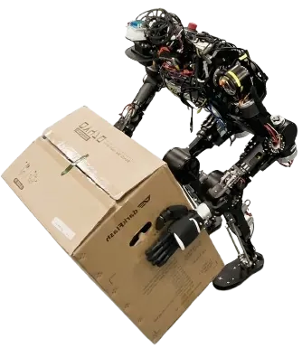
Figure 5: During hardware trials, the arms maintain the grasp while corrective torques remain in the legs.
Experiments
The real robot has 28 degrees of freedom: seven per arm and six per leg. Centroidal MPC runs at 50 Hz. The adaptive control layer runs at 500 Hz. Low-level torque control runs above 1 kHz. MuJoCo validates individual modules, while hardware experiments test static lifting and combined lifting-walking.
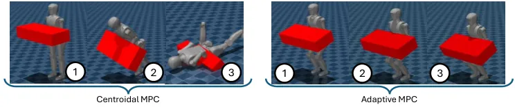
Figure 6: The standard MPC falls forward under a heavy unknown load; the adaptive MPC lowers its posture and preserves the stability margin.
| Method | Locomotion | Physical Constraints | Adaptive Balancing | Posture Planning | Application |
|---|---|---|---|---|---|
| Reduced-order MPC | Yes | No | No | No | Robust locomotion |
| MPC + WBC | Yes | Yes | No | No | Dynamic locomotion |
| Matrix exponential MPC + WBPC | Yes | Yes | No | No | Locomotion |
| Flexible MPC | Yes | Yes | No | No | Variable-speed walking |
| NMPC + gait adaptation | Yes | Yes | Yes | No | Posture and push recovery |
| Kinodynamic MPC + Gait-Net | Yes | Yes | Yes | No | Terrain walking |
| Three-particle MPC + WBC | No | Yes | No | Yes | Precise whole-body squat |
| This work | Yes | Yes | Yes | Yes | Unknown-payload loco-manipulation |
Table 1: The contribution is the combination of locomotion, constraints, adaptive balancing, and posture planning.
Static Lifting
Hardware tests use 7 kg and 10 kg payloads. In the 7 kg trial, the robot begins lowering and pitching at roughly 30 s, completes sitting in about 3 s, grasps the object, and stands between 55 s and 80 s before placing it down. The pelvis height, pitch, and leg joint curves are smooth, showing that jerk continuity is present in the generated reference.
The 10 kg trial exposes the compensator more clearly. The robot bows at about 20 s and grasps near 30 s. After pickup, the larger mass changes torso dynamics and causes small oscillations in pelvis height and pitch. The fuzzy controller increases corrective effort until pitch stabilizes; the robot then continues height recovery to its nominal posture. No payload estimate is reported as a prerequisite for recovery.
| Scenario | Payload | Timing | Observed Behavior |
|---|---|---|---|
| Static lifting | 7 kg | Squat at 30 s, 3 s sit phase, stand at 55–80 s | Smooth pelvis transitions and final placement |
| Static lifting | 10 kg | Bow at 20 s, grasp at 30 s | Small oscillations during pickup, then stable recovery |
| Lifting and walking | 7 kg | Grasp at 83 s, home at 110 s, walk 140–155 s | Stable carrying, stopping, and placing |
| Simulation | Unknown heavy object | Failure stages 1–3 for baseline | Adaptive MPC lowers posture and preserves CoM margin |
Table 2: The paper reports behavior and timing rather than a single headline score.
Carrying While Walking
In the combined scenario, the robot grasps a 7 kg object at 83 s, returns to home posture by 110 s, walks from 140 s to 155 s, stops, places the object, and returns to home. The fuzzy parameters were not retuned for walking. That observation matters: if the compensator only worked for the static task, it would be a task-specific patch. Reusing the same parameters across lifting and locomotion suggests that capture-point error is a more transferable signal than payload identity.
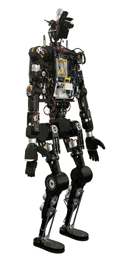
Figure 7: The platform used for both static lifting and walking manipulation.
| Module | Input Signal | Output | Key Constraint | Role |
|---|---|---|---|---|
| Centroidal MPC | Pelvis reference, contact mode, CoM state | Motion and wrench references | Friction cone, CoP, joint limits | Nominal feasible motion |
| Inverse-dynamics WBC | Joint error, contact wrench | Joint torque | Exponential tracking | Fast low-level conversion |
| Fuzzy balance controller | Capture-point error, CoM velocity, integral | Pitch and roll moment | 125 rules per axis, bounded output | Residual mismatch rejection |
| Torque allocation | Task-space compensation | Stance-leg torque increment | Minimum norm, stance legs only | Protect grasp and swing foot |
| Posture planner | Pelvis height, pitch, support polygon | Squat trajectories | Triple integrator, jerk and CoM bounds | Feasible feedforward motion |
Table 3: Each module consumes signals it can measure directly.
Limitations
The fuzzy rule base and Gaussian parameters are hand designed. The authors explicitly state that the parameters were tuned by expert experience and that a quantitative comparison with PID is left for future work. Thus, the result is convincing on the tested platform but not yet a validated transfer rule.
Capture-point error relies on a linear inverted pendulum abstraction. A large object can add substantial angular momentum and coupled inertial effects. For very heavy or awkward payloads, pitch and roll moments allocated to the legs may not cover all failure modes.
The allocation map $\Omega$ assumes that stance-leg joint torques can be related reliably to a pelvis task-space moment. Real actuators introduce friction, compliance, and estimation error. The paper does not evaluate online correction of this map.
The posture model is planar and three-link. It captures the dominant squat geometry but not arbitrary upper-body motions, yaw changes, lateral entry under a shelf, or contact changes caused by unusual payloads.
There is no official code release and no standardized benchmark table. Evidence is presented through successful simulations, timelines, and trajectory plots. Direct quantitative comparison with disturbance observers, model-reference adaptive control, or robust control remains open. The authors themselves point to learned compensation strategies and proactive disturbance observers as future work.
Takeaway
The paper is strongest as an engineering decomposition. MPC supplies constraint-aware nominal motion. Fuzzy control supplies a bounded residual correction without waiting for a payload estimate. Posture planning moves the pelvis to a place where the nominal motion can succeed. The lessons generalize: do not force one optimizer to absorb every uncertainty; connect compensation to observable stability margins; and encode smoothness as dynamics rather than filtering it afterward.
With learned rule parameters and a proactive disturbance observer, this framework could become more capable in highly dynamic handling. Even without those additions, the hardware result shows a practical route to humanoid lifting under unknown payloads.
Golden sentence: A nominal optimum is useless if the next capture point is already outside the support polygon; the controller must correct where the robot is falling, not merely what it was supposed to track.
SOURCE LINKS