mekion/the-bimo-projectApache-2.0 Bimo: a 45 cm Open-Source Hip-Head Biped Trained in Isaac Lab and Distilled onto an RP2040
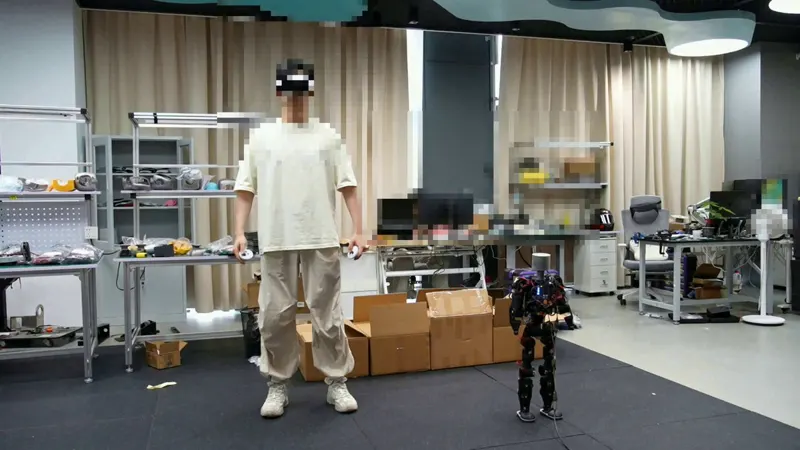
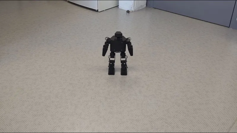
Bimo is a 45 cm, roughly 1.6 kg hip-head biped kit: eight STS-3215 bus servos, a BNO08x 9-DoF IMU, four VL53L0X rangefinders, two 180-degree cameras, and a custom RP2040 board closing a 20 Hz control loop. The repository publishes the Python control API (1023 lines), three MCU firmware builds (1349 lines), a ROS2 wrapper (1431 lines) and an Isaac Lab training environment (874 lines: six reward terms, dense domain randomization, and a system-identified STS3215Actuator with 3.113 Hz bandwidth, directional gear backlash and a 5 ms bus delay), plus a 26MB Bimo.usd model. The CPG gait's 104 Fourier coefficients and per-joint amplitude gains are hardcoded in both Python and C, and a [256,128,64] PPO teacher distills into a [64,32] student that goes through onnx2c into the firmware, so the robot walks untethered on the MCU. All code is Apache-2.0, but the CAD and electronics the README promises are still marked coming soon: no STL, STEP, schematic, gerbers or BOM exist in the working tree or in git history, and neither release ships pretrained weights (zero assets) or a DIY assembly manual. Currently v1.1.0 with 198 stars, in pre-order status.
Bipedal robotsHumanoidOpen Source
 0:23
0:23