
OPEN SOURCE DEEP DIVE
YHorizon-JM: A Replicable 57 mm Non-commercial Joint Actuator
A 57 mm, roughly 300 g non-commercial joint actuator that publishes its mechanics, driver board, FOC firmware, CAN protocol, and host tools, including vernier position recovery but not yet complete protection.
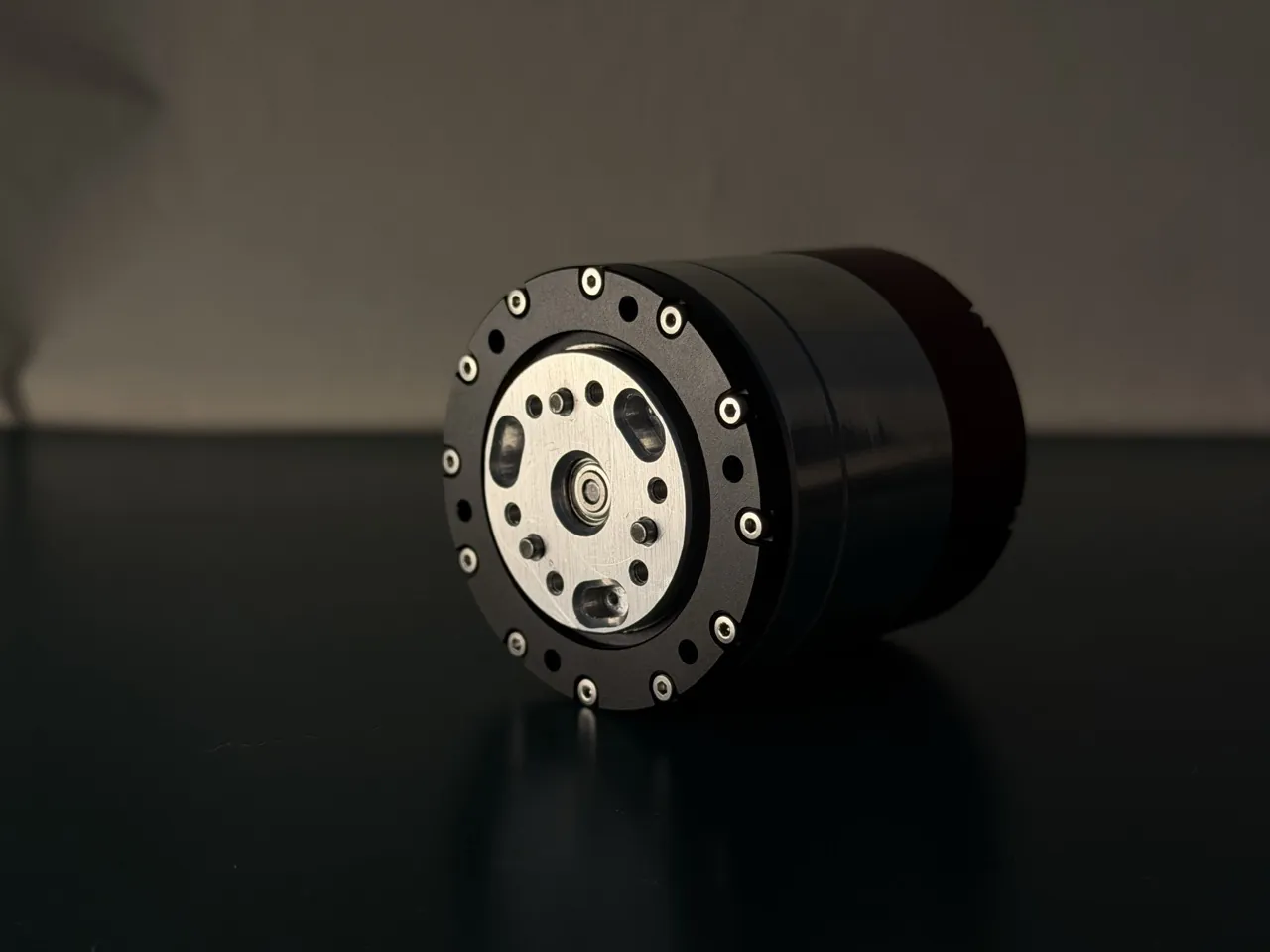
YHorizon-JM is a joint actuator prototype that publishes the mechanical parts, driver board, firmware, CAN protocol, and host tools together. It is not an appearance-only mockup or an off-the-shelf servo placed inside a custom shell. A 57 mm diameter, 52 mm thick, roughly 300 g package contains a WK4310 brushless motor, an 8:1 planetary reducer, dual encoders, a three-phase power stage, and a controller board. The project is most useful because the evidence chain runs continuously from magnetic encoder samples to CAN frames and from the low-side current-sampling window to the position-loop deceleration profile.
A prototype whose implementation can be inspected end to end
The repository is YHorizon-Robot/YHorizon-JM. Its current firmware, SDK, and tools target the first prototype: a GD32F303 controller and Classic CAN at up to 1 Mbps. The authors do not present later plans as shipped features. A move to the GD32C113, CAN FD, multi-axis synchronization, complete fault protection, and measured torque feedback all remain future work. This revision is therefore best treated as a reference for mechanical assembly, field-oriented control, a small CAN device protocol, and bench testing, not as a production actuator that can be deployed without substantial redesign.
| Layer | Published material | What a builder must verify |
|---|---|---|
| Mechanics | Assembly STEP, CNC parts, gear drawings, mechanical BOM | Bearing fits, planet-carrier alignment, output concentricity, and tapped-hole variation from local machining |
| Electronics | EasyEDA Pro source, schematic, Gerber, component BOM | Power-stage cooling, bus-voltage range, low-side sensing network, and SWD programming access |
| Firmware | GD32F303 control loop, SVPWM, encoder handling, current loop, state machine, and calibration | The WK4310 resistance and inductance must match the actual motor |
| Software | CAN protocol document, Python pack and parse layer, CLI and GUI host tools | Position and velocity are output-shaft quantities, and every real-time frame must match the active mode |
Publishing the whole stack removes much of the usual interface guesswork, but it does not remove the assembly barrier. The project calls for an arbor press, Loctite threadlocker or retaining compound, hex keys, a small Phillips screwdriver, and 0.8 mm insulation-displacement wire for the programmer. It also warns that the CNC parts are not guaranteed to match the authors' hardware; holes and fits may need adjustment. For a package containing a planetary train, bearings, and magnetic encoders, those are functional prerequisites rather than optional assembly notes.
Mechanical envelope and operating claims
The current prototype is 57 mm in diameter, 52 mm thick, and about 300 g. It uses a 14-pole-pair WK4310 motor followed by an 8:1 planetary reducer. Output speed is one eighth of motor speed, while output torque is approximately eight times motor torque before transmission losses. The project lists 3 Nm continuous torque, 6 Nm peak torque, and a maximum 48 V supply. It does not provide a combined thermal envelope covering motor heating, driver temperature rise, reducer life, mounting conditions, and ambient airflow. A demonstrated peak torque is not the same as a guaranteed continuous rating under arbitrary duty cycles.
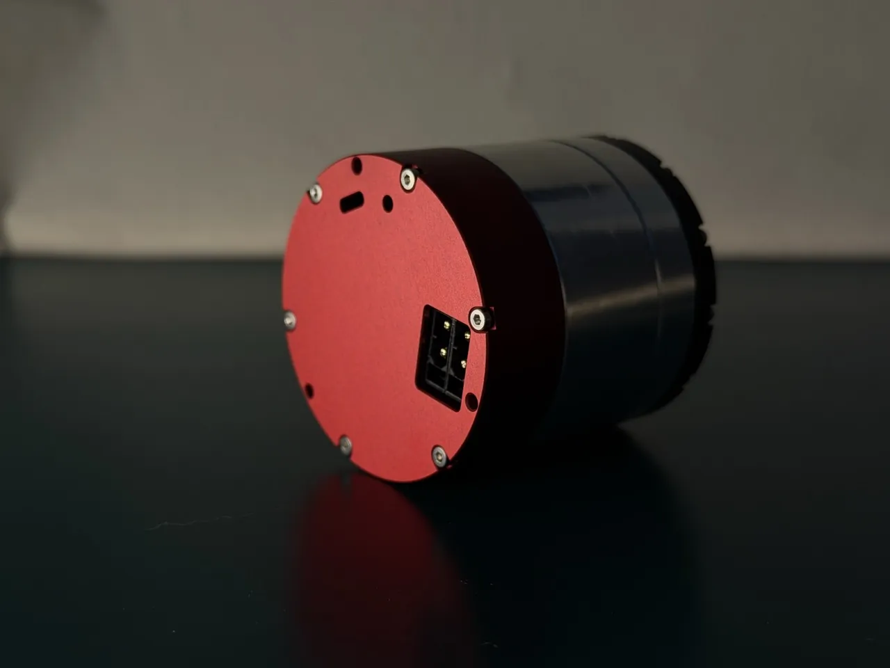
The mechanical directory provides a traceable assembly rather than an illustrative shell. The top-level assembly is mechanical/asm/YHorizon-JM-asm.STEP. CNC models are split into the output end cap, lower end cap, rear housing, motor output disk, ring-gear support, and planet carrier. Gear drawings live under mechanical/gears/. A builder can therefore check the relationship among tooth counts, bearing seats, planet carrier, and output disk instead of relying on an exploded rendering.
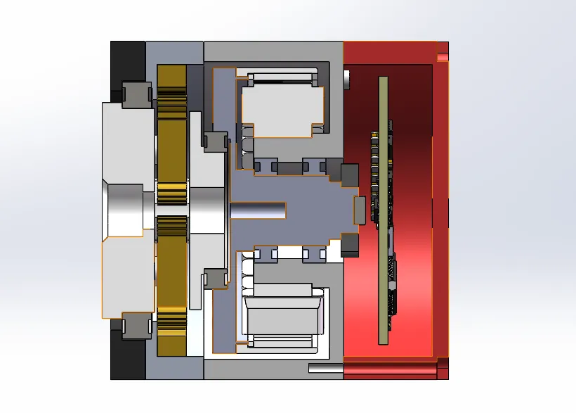
Small joint actuators rarely fail first because the motor cannot turn. They fail because after assembly there is excess friction, shaft eccentricity, axial preload, encoder misalignment, or insufficient planet-carrier stiffness. Gear backlash, output-disk runout, and the gap between each magnetic sensor and its magnet all change the load seen by the control loops. No current-loop tuning can identify an over-preloaded bearing. A replicated actuator should therefore begin with low-voltage, low-speed, unloaded tests, followed by gradual checks of temperature, acoustic noise, backlash, and position repeatability. High-gain position parameters must not be copied into a newly assembled unit before those checks.
Recovering multi-turn position with two encoders
The first revision uses two MT6701 magnetic encoders and a 30-tooth, 31-tooth vernier arrangement to recover motor-shaft multi-turn position. Either encoder alone measures only one motor revolution. Because one output revolution equals eight motor revolutions, forgetting the motor-shaft branch would make the actuator lose position after a single output turn. The relatively prime 30 and 31 tooth counts create a residue pattern that remains unique over 31 motor revolutions and then repeats.
The implementation is in firmware/Foc/foc_vernier.c. Both encoder readings are normalized and the code computes residual = frac(v + (30/31)u). The residual is quantized into 31 candidate sectors, and a tolerance check rejects an inconsistent sample. The recovered motor-shaft angle is multiplied by 0.125 to produce output-shaft position. Thirty-one motor turns divide into approximately 3.875 output turns; beyond that span, the vernier combination itself repeats, and the firmware relies on incremental tracking from continuous motion to extend the position.
| Quantity | Implementation | Meaning |
|---|---|---|
| Encoder pair | Two MT6701 sensors | One measures the main motor-shaft angle; the other measures an angle coupled to the 31-tooth path |
| Tooth counts | 30 and 31 | Relatively prime, producing 31 distinguishable sectors |
| Unambiguous span | 31 motor revolutions | About 3.875 output revolutions before the absolute pattern repeats |
| Velocity estimate | 500 Hz second-order low-pass filter | Converts differentiated electrical angle into filtered mechanical velocity |
| Missed sample | Prediction from the previous velocity | Advances one control period instead of introducing an immediate angle jump |
Two details are easy to miss. First, the absolute-position calculation begins on the motor shaft; the output value is derived afterward by dividing by the gear ratio. Second, the firmware is not an unlimited absolute recorder. The vernier pair supplies an absolute seed over 31 motor revolutions, and incremental tracking carries position across that window. If the output is externally rotated out of the recoverable range while power is off, or if the sensor-to-gear alignment changes during assembly, calibration must be repeated.
Electronics and low-side current measurement
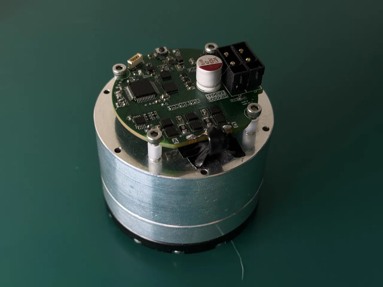
The controller uses a GD32F303CCT6 running at 112 MHz. An FD6288 drives the three-phase bridge. PWM switching is 20 kHz, the outer control loop runs at 4 kHz, and the current-loop target bandwidth is 500 Hz. The firmware takes the WK4310 line-to-line resistance of 10.32 ohm and inductance of 4.76 mH, halves both for the star-equivalent phase values, and calculates the PI gains from the target bandwidth. This is an important detail for replication: a motor with different electrical parameters may oscillate with the default gains or respond too slowly.
The first revision senses current in the low-side shunts. Two phases use 1 milliohm shunts and a current-sense gain of 20. The ADC uses a 1.5-cycle sample aperture, and the trigger must fall inside the brief interval when the low-side switch is on. The configuration records approximately 98 ns of dead time and adds a wait of roughly 112 timer clocks before conversion starts. At startup, the firmware averages 32 samples for each phase to estimate the zero-current offset, falling back to an ADC midpoint of 2048 if no samples succeed. Bus voltage is read through a resistor divider every 5 ms and used to normalize the current-loop PI feedforward.
| Item | Current implementation | Engineering consequence |
|---|---|---|
| Control and gate drive | GD32F303CCT6 and FD6288 | 112 MHz control and a three-phase half bridge |
| Modulation | 20 kHz PWM and 4 kHz outer loop | Five PWM periods per outer-loop update |
| Current sensing | 1 milliohm, gain 20, 1.5-cycle aperture | Valid only inside the low-side conduction window |
| Current bandwidth | 500 Hz target | PI values depend on measured motor resistance and inductance |
| Shipped protection | Bus measurement, current offsets, calibration fault bit | No over-current, over-voltage, temperature, or stall protection |
Low-side sensing is sensitive to timing. Near full modulation, with a long dead time, or when a command leaves only a narrow low-side window, the ADC may miss the real phase current. The repository states that the design works within its configured voltage limit, but that is not a characterization across every bus voltage, temperature, and duty cycle. A replication should first inspect the trigger and phase-current waveform with an oscilloscope before trusting the current values reported by the firmware.
The current loop is the compile-time default. Voltage mode remains available through CFG_INNER_LOOP_VOLTAGE. Changing the motor without changing the PI calculation is not supported by evidence in the repository. Voltage mode is not automatically safer either: it removes closed-loop current regulation, so the outer command directly becomes a quadrature voltage. The scale and meaning of velocity and position gains also change, requiring a fresh tuning pass.
From current control to the three outer modes
The 20 kHz PWM interrupt reads the main encoder, calculates electrical angle, updates the current PI controllers, performs inverse Park transforms, and applies space-vector modulation. A 4 kHz control interrupt maintains the vernier multi-turn state, computes output-shaft position and velocity, and produces the torque command. In current mode, the outer-loop output t_ref maps to a quadrature-current reference as Iq_ref = t_ref * I_LIMIT / V_LIMIT. With 5 A and 0.5 per unit, t_ref = 0.5 maps to 5 A, and the reachable command is approximately plus or minus 5 A.
The protocol document describes the mapping as 10 A per per-unit. That arithmetic comes from 5 A divided by 0.5, but the output is also clamped to plus or minus 0.5 per unit. The effective current-command range is therefore plus or minus 5 A, not plus or minus 10 A. A host that converts amperes directly by the larger number can underestimate the command amplitude. A clearer statement would be "1 per unit represents 10 A mathematically, while the currently configured reachable range is plus or minus 0.5 per unit."
| Mode | Outer-loop calculation | Important behavior |
|---|---|---|
| Motion | t_ref = Kd * velocity error + Kp * position error + feedforward | Gains are volatile and provide stiffness plus damping; feedforward is limited to plus or minus 1 per unit before the final command clamp |
| Velocity | Velocity error passes through a PI controller | Integral and output are limited to 0.5 per unit; commands and feedback use output-shaft radians per second |
| Position | A position PID creates a velocity reference, then the velocity PI creates the torque command | A square-root speed limit handles large errors, a PID blend takes over near the target, and position integration stops while the inner loop saturates |
Position mode is more than proportional position control. The code uses maximum velocity and a default acceleration term to create a speed constraint for the approach. Far from the target, the command follows a profile proportional to the square root of 2 * acceleration * absolute error. Closer to the target, the reference blends into a position PID. The velocity PI runs underneath and includes conditional anti-windup. A first-time builder should still begin with conservative position gains and inspect unloaded and lightly loaded step responses before increasing stiffness.
All position, velocity, and motion-feedback quantities use output-shaft coordinates. The t_ref in motion feedback is a torque command, not measured torque. The hardware has no torque sensor and no production calibration from phase current to output torque. The protocol also has no separate measured-Iq field. A host that needs current telemetry must use the debug interface or extend the protocol.
CAN V1.0: strict framing without a command watchdog
The communication layer uses Classic CAN 2.0 with standard 11-bit identifiers, fixed eight-byte data frames, 1 Mbps, and node IDs from 1 through 63. Real-time commands, gains, management requests, feedback, status, and calibration progress occupy different identifier ranges. Motion, velocity, and position commands use 0x100, 0x140, and 0x1C0 plus the node ID. Feedback uses 0x300 plus the node ID. All values are little-endian.
| Step | Host action | Device response or constraint |
|---|---|---|
| Power on | Wait for calibration or query status | Success enters RUNNING; failure enters FAULT; there is no separate ENABLE command |
| Select mode | Send SET_CONTROL_MODE | Integrators and torque command are cleared; a matching real-time frame is still required |
| Set gains | Write mode-specific values to the 0x180 range | Invalid modes or nonzero reserved gains are rejected while previous values remain active |
| Stream control | Send the motion, velocity, or position frame for the active mode | Only the last valid real-time frame in one receive pass is applied; feedback is returned on 0x300 |
| Stop | Send zero velocity, hold the current position, or remove power | There is no command timeout; the last command remains active after the host disappears |
The absence of a command timeout is one of the most important behaviors in this firmware. A brief CAN interruption, a crashed host process, or a broken control loop does not automatically return the motor to zero. The actuator holds the last valid command until a new command in the same mode, a mode change, calibration, a fault, or power removal. A bench setup therefore needs a hardware emergency stop and independent power isolation. A complete robot must treat communication heartbeats, watchdogs, and hardware protection as system-level requirements rather than assuming that the joint will stop itself.
There is no ENABLE or DISABLE command. The management table accepts set-zero, clear-calibration-fault, start-calibration, set-mode, set-node-ID, save-user-parameters, get-status, and get-gains. Unknown commands, including legacy enable or disable numbers that another actuator ecosystem may use, return INVALID_COMMAND. This reduces state-machine ambiguity, but integrators must follow the implemented V1.0 protocol instead of transferring conventions from a different vendor.
If several real-time frames appear in one receive pass, only the last valid frame is applied. This prevents the controller from trying to execute stale commands, but it also means that high-rate transmission does not create a command queue. Intermediate frames are not replayed. A real-time frame for a different control mode is silently dropped without an error response. A host should wait for a mode-change acknowledgment before streaming that mode and should treat missing feedback as a system-level fault.
Calibration, zero position, and fault recovery
Encoder calibration is a blocking operation. After START_ENCODER_CALIBRATION, the drive acknowledges the request, enters CALIBRATING, and occupies the main loop for several seconds. The process aligns the motor and performs prechecks, rotates forward and backward by about four electrical revolutions in each direction, estimates pole pairs, direction, and electrical offset, and saves the result to nonvolatile memory. Progress is reported roughly every 50 ms and immediately on stage changes. When calibration returns, pending real-time frames are discarded.
A failed calibration enters FAULT and sets the calibration-fault bit. Only bit 10 is currently used. CLEAR_FAULT clears that one condition, but it does not restore motion: the state returns to RUNNING while PWM remains off, and another calibration is required before motion. This avoids the dangerous shortcut of clearing a fault and immediately resuming a loaded joint. It also means that a host must distinguish "state says RUNNING" from "the output has been safely enabled."
Saving user parameters, setting the node ID, and setting zero position briefly stop CAN while Flash is programmed, after which the controller restarts. Node IDs can be changed from 1 through 63. An on-board button also enters an ID-edit mode, with LED blink patterns representing tens and ones. Zero position and velocity and position gains can be stored. Motion-mode gains remain in RAM only. The firmware has no temperature measurement, over-current comparator, over-voltage protection, stall detector, or unsolicited fault broadcast. The status temperature field is currently fixed at zero. A surrounding system must supply those missing protections.
Build, flash, and host workflow
The firmware builds with arm-none-eabi-gcc, CMake, and Ninja. The output is firmware/build/gd32f303/YHorizon-JM.elf. The repository includes Linux and Windows setup, build, and flash scripts. Programming uses CMSIS-DAP over SWD. Distributions usually lack an OpenOCD driver named for GD32F30x, so the tools fall back to a compatible configuration and explicitly avoid a full-chip erase. Before flashing, confirm that the device-capacity setting, startup file, and linker script match the physical MCU.
The Python host tools under sdk/python/ use python-can with SocketCAN or serial CAN adapters. The command-line client can set motion gains, stream position, velocity, and feedforward commands, and parse feedback, acknowledgments, status, and calibration reports. The protocol module also converts t_ref to an equivalent quadrature current or voltage. A first bring-up should use listen-only operation to confirm state, bus voltage, and error codes before the host sends gains or any motion command.
The engineering gaps that matter most
The strongest part of the project is also the reason it must be used carefully. The hardware and software chain is unusually complete for a prototype, but the first revision still lacks measured output torque, temperature sensing, over-current protection, over-voltage and undervoltage protection, stall detection, unsolicited fault events, and communication-timeout shutdown. The safety document requires a hardware emergency stop and says not to run near people at full power before current limits, over-current behavior, and emergency stopping have been verified. That is a design requirement, not just boilerplate.
The documentation also contains a real drift. The opening paragraph of the English README still describes the first revision as a voltage-mode servo, while the specification table, protocol document, and config.h show that current mode is the default and voltage mode is a compile-time fallback. Replicators should derive behavior from the source and configuration, while treating the prose mismatch as evidence that the project evolved quickly. The previously described 10 A per unit wording needs a similar correction: the conversion scale and the clamped reachable range should be stated separately.
Power-up at 48 V requires more than changing a nominal parameter. The repository lists a maximum 48 V supply, but the default nominal bus is 24 V. A 48 V build must check power-device ratings, capacitors, the bus divider, thermal design, and connected-motor insulation. First bring-up should use a lower bus voltage, conservative current limits, and constrained mechanical travel. Calibration, direction, zero position, feedback sign, and the emergency stop should all be verified before the actuator drives a rigid load.
License: public source does not mean unrestricted commercial open source
The repository calls itself open source, but the actual rights combination is better described as source-available open hardware. The mechanical and hardware directories use CC BY-NC-SA 4.0. Firmware, SDK, and tools use GPLv3. The top-level license and README then state that the entire project is for non-commercial study and exchange, regardless of the directory license. GitHub reports the repository license as NOASSERTION, which reflects the fact that automated detection cannot map this layered set of terms to one standard license.
| Material | Path | Stated license | Additional restriction |
|---|---|---|---|
| Mechanical and electronic hardware | mechanical/, hardware/ | CC BY-NC-SA 4.0 | Commercial use prohibited; derivatives require attribution and the same license |
| Firmware, SDK, and tools | firmware/, sdk/, tools/ | GPLv3 | The top-level files add a project-wide non-commercial restriction |
| Documentation and unspecified content | Other paths | Defaults to CC BY-NC-SA 4.0 | Third-party files retain their own stated terms |
For personal study, FOC experimentation, and a one-off bench actuator, the repository provides an unusually complete set of materials. A product program, contract manufacturer, reseller, or paid integration should not assume that the GPLv3 directories override the project-wide commercial restriction. The authors provide a separate commercial-contact route, which indicates that such use requires another agreement. Engineering feasibility and legal permission are independent questions: working code does not by itself grant the right to ship it in a commercial product.
Who should study it, and what comes next
YHorizon-JM is relevant to three groups. The first wants to understand how mechanical parts, magnetic encoders, and a power stage become a complete robot joint. The second wants a concrete study of low-cost FOC, low-side current sampling, and vernier position recovery. The third already uses commercial actuators and wants to compare CAN protocols, control state machines, and safety boundaries. It is not an appropriate first system for operation near people, and it should not be connected directly to a high-load manipulator without assembly and protection validation.
The authors' next-step list is a GD32C113 controller, CAN FD, multi-axis synchronization, explicit enable and disable, over-current and over-voltage protection, temperature protection, stall detection, measured torque, and unsolicited fault events. That list identifies the real limitations of revision one. The main constraint is not raw computation; it is the combination of single-axis communication and missing system-level safety behavior. The actuator becomes much more suitable as a multi-joint robot building block only after those layers exist.
As a first prototype, the project's value comes from keeping the evidence chain together. A reader can follow the STEP assembly into the power board, trace the ADC trigger into the current PI, follow a CAN frame into the position loop, and read the resulting state with the Python tools. The same repository also makes the distance to a product visible: calibration blocks the main loop, communications have no timeout, protection is incomplete, and commercial use is prohibited. Understanding those constraints along with the performance numbers is the most reliable way to use the design.
SOURCE LINKS