

Six Months to Become a Robotics Engineer: A Build-First Path from Circuits to Embodied AI
Follow a build-first six-month route from electronics, motors, CAD and ROS 2 to control math and LeRobot, turning 27 projects into verifiable robotics evidence.
Robotics looks like five fields stacked on top of each other. One person begins with a university textbook and stops at rotation matrices. Another buys an Arduino kit, blinks an LED, and never builds the second circuit. Someone else follows ROS 2 tutorials without understanding PWM, then cannot explain why the real motor behaves nothing like the simulator. A fourth studies only machine learning and can train a policy but cannot make a joint move safely.
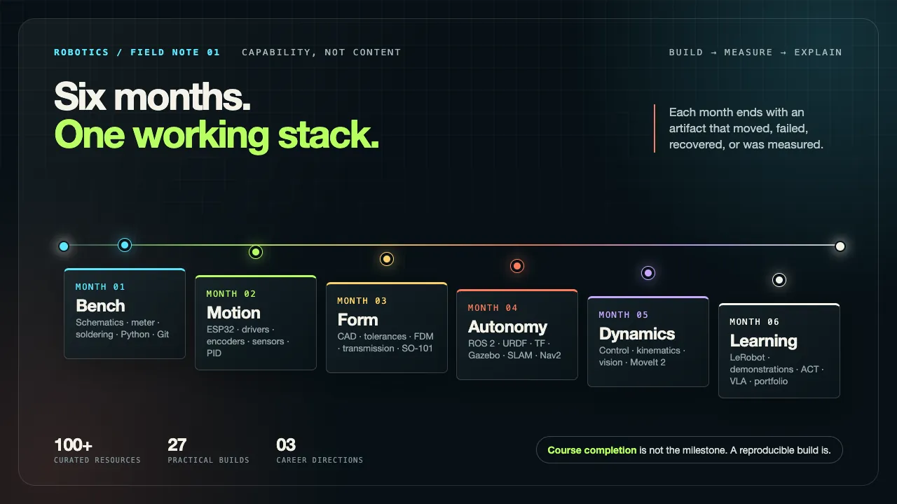
This roadmap is a way out of that fragmentation. It is adapted from Ronin's long-form guide “How to become a Robotics Engineer in 6 months (RESOURCES)”, but its organizing idea is stronger than a list of courses: every month must produce a robot, measurement, or debugging record that another engineer can inspect. The route starts at the electrical bench, moves through motion and fabrication, reaches the ROS 2 autonomy stack, adds the control mathematics underneath it, and ends with learning from demonstrations and a portfolio that survives technical follow-up questions.
A robotics portfolio is made of things that moved, measurements you can defend, and failures you can explain. Course completion is not the artifact.
The source contains nearly 12,000 words, more than 100 linked resources, and 27 practical builds. Its prices and links were checked by the author in September 2026. This edition preserves those claims while labelling them as time-sensitive vendor observations, not permanent market facts. It assumes about two or three focused hours per day, and it explicitly does not promise that six months will make anyone a senior robotics engineer.
Why robotics is different from another AI application
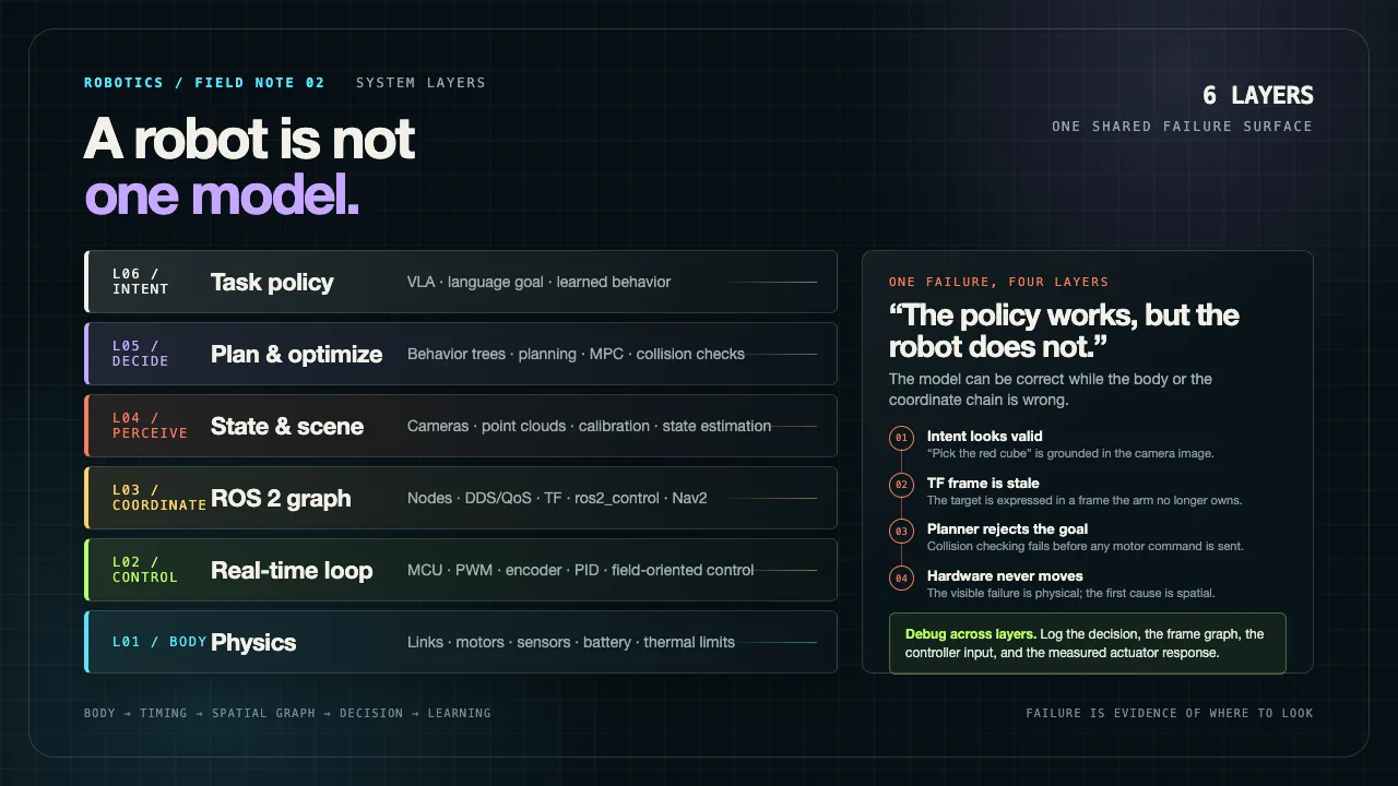
The author argues that the strategic opportunity is not another software wrapper. Models increasingly exist; the scarce work is connecting perception, decisions, timing, electricity, and mechanical structure inside a physical body. Real-world data cannot simply be scraped at internet scale. A gripper that slips may have no searchable error message. A falling robot creates consequences that cannot be delegated to a background job.
That does not mean “robotics is empty” or that every learner will be hired. It means the leverage comes from integration and evidence. The guide treats the physical world as the source of a durable skill: you have to observe the machine, isolate the layer that failed, change one thing, and measure the result.
What a robotics engineer actually does
“Robotics engineer” is not one job. The field includes perception and computer vision; controls and state estimation; motion planning and manipulation; robot learning; embedded systems and firmware; simulation; systems integration; and deployment or operations. The realistic goal is depth in one specialty plus enough literacy to debug across the others.
After reviewing live listings from Figure and Skild, the author found four repeated requirements: both C++ and Python; experience on real hardware; one area of depth with broad literacy elsewhere; and debugging treated as a skill in its own right. A specific degree was not universal. The roadmap therefore optimizes for demonstrable capability rather than collecting certificates.
Month 1: Electronics, instruments, and the bench
Outcome: read a schematic, build the circuit, and locate the fault when it does not work.
Many roadmaps begin with an Arduino tutorial because it produces motion quickly. That skips the layer that explains brownouts, floating inputs, shorted rails, and a motor that draws more current than the regulator can supply. You do not need to derive analog integrated circuits from first principles. You do need working fluency in voltage, current, resistance, power, switching, decoupling, and the meaning of a schematic.
Electrical fundamentals
Start with a simulator. Wiring a circuit incorrectly there costs nothing and exposes the consequence. Build every example rather than watching hours of video without touching a component.
- Falstad Circuit Simulator animates current and colours live voltage, making electrical flow easier to inspect.
- Tinkercad Circuits combines a virtual breadboard, Arduino, and multimeter, which is useful before buying parts.
- All About Circuits: Lessons in Electric Circuits is a free multi-volume reference for the concepts a video may hand-wave.
- Afrotechmods offers short beginner-to-advanced demonstrations for learners who dislike lecture format.
- Make: Electronics, 3rd edition by Charles Platt was priced at $29.99 at the time of the source article.
Ohm's law and the voltage divider should become automatic:
$$V = IR \qquad V_{\mathrm{out}} = V_{\mathrm{in}}\frac{R_2}{R_1 + R_2}$$
A divider is not a magical 3.3 V converter. It has output impedance and wastes current. That distinction matters when a sensor input or microcontroller load changes. Power follows $P=VI=I^2R$, so a stalled motor can turn a seemingly comfortable supply into heat and a voltage sag:
$$I_{\mathrm{stall}}=\frac{V_{\mathrm{supply}}}{R_{\mathrm{winding}}},\qquad P_{\mathrm{heat}}=I_{\mathrm{stall}}^2R_{\mathrm{winding}}$$
Focus on current draw, pull-up and pull-down resistors, decoupling capacitors, transistor switching, LiPo cell count and C rating, safe charging, and the standard schematic symbols for resistors, capacitors, diodes, transistors, supply rails, and ground.
Bench budgets and verified starter hardware
| Tier | What it buys | Author's September 2026 estimate |
|---|---|---|
| 0 | Browser simulators and free references | $0 |
| 1 | Solderless starter kit and multimeter | Roughly $45–$60 |
| 2 | Soldering iron, solder, cutters, strippers, helping hands, perfboard, passives | Roughly $110–$160 |
| 3 | Bench supply, better meter, desoldering pump, storage, chassis kit | Roughly $200–$300 |
| Item | Price cited | Why it appears |
|---|---|---|
| Elegoo UNO R3 Super Starter Kit | $42.99 | Broad lesson kit with Arduino-compatible board and modules |
| Elegoo UNO Basic Starter Kit | $19.99 | Lowest practical starting point when budget is tight |
| SparkFun Inventor's Kit v4.1.2 | $99.95 | Strong curriculum and project sequence |
| Adafruit 9205B+ multimeter | $17.50 | Voltage, current, resistance, capacitance, and continuity |
| Pinecil V2 | $25.99 community / $35.99 retail | Temperature-controlled USB-C soldering iron |
Where to buy changes the learning loop. AliExpress can be much cheaper but has long shipping and weak recourse. Amazon is faster for a first kit. Elegoo ships from regional warehouses. Adafruit and SparkFun cost more, but their product pages include maintained tutorials and real support. Seeed Studio and DFRobot ship globally from China. DigiKey and Mouser are for exact components and datasheets. Pololu is particularly strong for motors and drivers.
Soldering, Python, the shell, and Git
A loose jumper is not a reliable robot. Learn to tin a tip, heat the joint rather than the solder, recognize a cold joint, use flux, and remove a component without lifting pads. The Adafruit soldering guide covers technique and failure photographs; the SparkFun multimeter guide explains voltage, resistance, current, continuity, and fuse mistakes.
Python, the terminal, and Git are not side quests. They are used every week. Useful resources include:
- CS50P for a structured Python course with problem sets and a final project.
- Python for Everybody for a gentler entry point.
- The Missing Semester for shell, scripting, environment variables, and the command-line fluency omitted by many courses.
- Learn Git Branching for an interactive visual model of branches and merges.
Practice Python functions, classes, file I/O, JSON, virtual environments, and package installation. Learn to run scripts, inspect logs, set environment variables, and connect over SSH. Use Git branches, commits, remotes, and a README a stranger can follow.
Month 1 build gate
- Calculate and simulate a voltage divider, then verify it with a meter.
- Build a transistor switch that lets a logic pin control a larger load.
- Measure batteries, resistors, and continuity; find a wire you deliberately break.
- Solder and electrically test header pins, then remove and replace one joint.
- Publish a Python utility to GitHub with a photo, wiring or setup description, and one paragraph on what broke.
Milestone: you can move between schematic, calculation, physical wiring, measurement, code, and version history without treating them as separate subjects. You can explain why a motor stall can reset a microcontroller.
Month 2: Microcontrollers, motors, sensors, and the first moving robot
Outcome: build a robot that senses, moves, and corrects itself.
A line follower already contains the miniature version of a humanoid: sensor input, actuator output, a closed loop, timing constraints, and a tuning problem. It is cheaper to break and easier to observe.
Arduino first, ESP32 immediately after
Arduino remains useful because the ecosystem is enormous and beginner tutorials assume it. Learn digital and analog I/O, PWM, interrupts, debouncing, serial debugging, I2C and SPI, and non-blocking timing. Replace long delay() calls with a millis() scheduler; a blocking delay stops measurement, control, and communication at the same time.
- Paul McWhorter's Arduino Lessons provide slow, sequential teaching and homework.
- Arduino built-in examples are the shortest path from installation to a running sketch.
- Arduino Learn is an authoritative reference for I/O, PWM, I2C, SPI, and UART.
- Arduino Project Hub provides thousands of community projects with wiring and code.
Build a reaction timer: an LED fires after a random delay, a button stops the clock, debouncing and interrupt handling remove false events, and the result prints over serial. It is small enough to demonstrate in fifteen seconds and sophisticated enough to expose timing mistakes.
The ESP32 adds Wi-Fi, Bluetooth, more compute, and multiple cores at a low price. The guide recommends an ESP32-S3 as the main board plus one classic ESP32 for older tutorials.
| Board | Price cited | Role |
|---|---|---|
| ESP32-S3-DevKitC-1, 8 MB flash | $15.95 | Primary modern development board |
| Classic ESP32 Dev Board | $15.00 | Compatibility with older examples |
| Seeed XIAO ESP32-C3 | $4.99 | Very small embedded node |
Key resources include Random Nerd Tutorials, the official ESP-IDF guide, the Arduino-ESP32 core documentation, and the DroneBot Workshop ESP32 hub. Use the Arduino layer for speed, ESP-IDF when task, core, power, and timing control matter, and MicroPython for rapid sensor experiments rather than hard real-time balance loops.
Build a network service on the ESP32: live sensor readings in a browser plus controls that move a servo from a phone. This combines Wi-Fi, HTTP, asynchronous work, and physical output in one visible artifact.
Actuators are electrical and mechanical systems
| Actuator | Feedback | Typical first use | Important limitation |
|---|---|---|---|
| Brushed DC gearmotor | None unless an encoder is added | Differential-drive rover | Needs an H-bridge and explicit position sensing |
| Hobby servo | Internal, usually not exposed | Simple pan-tilt or linkage | Limited travel and poor load diagnostics |
| Smart serial-bus servo | Position, velocity, current, temperature | Low-cost robot arm | Bus configuration, IDs, voltage, and calibration matter |
| Stepper | Open-loop position by counting steps | Small linear stage | Can lose steps without detection |
The source advises learning the L298N because tutorials use it, then replacing it with a modern driver. The L298N is an older bipolar-transistor H-bridge that drops voltage, heats up, and wastes battery energy. Prefer the TB6612FNG or DRV8833 for small motors.
- DroneBot Workshop: DC motors and the L298N explains PWM, H-bridge operation, and joystick control.
- SparkFun TB6612FNG guide covers the driver recommended as the practical replacement.
- DroneBot Workshop: stepper motors covers unipolar and bipolar motors, microstepping, and drivers.
- SimpleFOC introduces field-oriented control for brushless motors.
| Part | Price cited |
|---|---|
| Adafruit DRV8833 driver | $5.95 |
| SparkFun TB6612FNG breakout | $14.77 |
| Pololu gearmotor with encoder | $19.95 each |
| Pololu A4988 stepper carrier | $8.95 |
| FeeTech STS3215 smart servo | $31.71 |
A gearbox trades speed for torque. Ignoring losses, the ideal relation is:
$$\omega_{\mathrm{out}}=\frac{\omega_{\mathrm{motor}}}{N},\qquad \tau_{\mathrm{out}}\approx N\eta\,\tau_{\mathrm{motor}}$$
The useful lesson is not the equation alone. Backlash, friction, compliance, and encoder placement determine whether the predicted output survives contact with the world. Drive one DC motor at five PWM settings, add an encoder, and command exactly one wheel revolution independent of battery voltage. That is the first nontrivial closed loop.
Sensors and state estimation
An accelerometer is noisy during motion but does not drift in the long term. A gyroscope is smooth over short intervals but integrates bias. A complementary filter combines them cheaply:
$$\theta_t=\alpha\left(\theta_{t-1}+\omega_t\Delta t\right)+(1-\alpha)\theta^{\mathrm{acc}}_t,\qquad \alpha\approx0.98$$
The source recommends writing this four-line filter before a Kalman filter. The point is to understand what each sensor contributes and why timing matters. A Kalman filter becomes meaningful once you can state the process model, measurement model, and uncertainty instead of treating it as a library call.
- Adafruit BNO085 guide demonstrates on-chip orientation fusion.
- Kalman and Bayesian Filters in Python provides runnable notebooks from g-h filters through EKF, UKF, and particle filters.
- MathWorks: Understanding Sensor Fusion and Tracking gives a six-part conceptual sequence.
| Sensor | Price cited | Trade-off |
|---|---|---|
| HC-SR04 ultrasonic | $3.95 | Cheap and wide, but poor on soft or angled surfaces |
| VL53L0X time-of-flight | $14.95 | Narrow 35-degree field of view and less double imaging |
| MPU-6050 6-DoF IMU | $12.95 | Cheap raw inertial sensing; fusion is your work |
| BNO085 9-DoF IMU | $29.50 | On-chip fusion and robotics-friendly UART mode |
| Pololu magnetic encoder pair | $8.95 | Adds odometry to a motor without built-in feedback |
| RPLIDAR C1 | $69.00 | Low-cost 360-degree lidar for indoor SLAM |
Mount an IMU, print pitch, hold it still, and watch the estimate drift. Add the complementary filter, then change the weight and explain the lag-versus-noise trade-off from the data.
Two robots, two lessons
| Build | Quality estimate | Budget estimate | Primary evidence |
|---|---|---|---|
| Line-following robot | About $105 | About $38 | P versus PD response; oscillation before and after |
| Self-balancing robot | About $134 | About $62 | Stable angle estimate, loop timing, and recovery behavior |
The quality line follower budget in the source includes an ESP32-S3, Pololu Romi chassis, TB6612FNG, QTR-8RC sensor array, battery, wiring, and headers. The budget version substitutes a generic ESP32, acrylic chassis, DRV8833, TCRT5000 sensors, and cheaper wiring. The balancing robot uses two encoded gearmotors, an IMU, driver, chassis, battery, charger, and wheels.
Build the line follower first. Film the best P-only response and the improved PD response under the same track and speed. The comparison proves that the gain change was deliberate. Then build the balancer; it exposes bad orientation, bad timing, saturation, and an unstable mechanical assembly all at once.
Month 2 build gate
- Move a motor at controlled duty and distinguish duty from measured RPM.
- Read an encoder and close a position loop.
- Wire an I2C sensor from its datasheet without following a recipe.
- Fuse accelerometer and gyroscope data into a stable angle estimate.
- Explain P, I, and D using measured robot behavior, not definitions alone.
- Publish both robots with wiring, code, videos, and a failure log.
Month 3: Mechanical design, CAD, and manufacturing
Outcome: model a part from a datasheet, manufacture it, and make it fit.
This is where kit assembly becomes robot design. Every later build should include at least one part that exists because you chose its geometry, tolerances, material, and manufacturing process.
Choose one CAD tool and go deep
| Tool | Advantage | Constraint |
|---|---|---|
| Onshape Free | Browser CAD, strong assemblies and mates, robotics learning path | Free documents are public |
| Fusion Personal | CAD, CAM, and additive manufacturing integration | Renewable personal-use licence with feature limitations |
| FreeCAD | Local and open source | Workflow and stability differ from commercial cloud CAD |
| SOLIDWORKS for Makers | Industry-standard modelling workflow | $48/year at the cited time; maker files have restrictions |
- Onshape Fundamentals: CAD is a structured path that ends with a credential and includes robotics material.
- Product Design Online: Fusion in 30 Days uses thirty modelled objects to build parametric confidence.
- MangoJelly FreeCAD tutorials are organized as focused lessons rather than one monolithic course.
- Protolabs Network: Design for 3D Printing covers walls, orientation, tolerances, supports, snap fits, and file formats.
Use fully constrained sketches. Drive dimensions with variables. Build assemblies with the same joint types as the mechanism: revolute, slider, and fixed. Design from the actuator datasheet rather than eyeballing a photograph. Export STEP for interchange and STL or 3MF for printing.
Practice: model a bracket for the exact servo you own, using its drawing and screw-hole geometry. Print it. Measure the error. The first fit may fail; that measurement is the lesson.
3D printing: process before printer
| Printer | Price cited | Relevant reason |
|---|---|---|
| Creality Ender-3 V3 SE | $199 | Low-cost open-frame FDM |
| Bambu Lab A1 mini | $219.99 | Small, beginner-friendly FDM |
| Bambu Lab A1 | $299.99 | 256 mm bed for larger brackets |
| Creality K1C | $369 | Enclosed and hardened extruder for abrasive materials |
| Bambu Lab P1S | $799 | Enclosed CoreXY for ABS and ASA |
| Material | Use it for | Failure mode to design around |
|---|---|---|
| PLA / PLA+ | Prototype brackets, jigs, the stock SO-101 structure | Creep under sustained load; softens around 55–60°C |
| PETG | Chassis plates, servo mounts, parts that survive impact | Stringing and different stiffness than PLA |
| ABS / ASA | Parts near heat and outdoor use | Warping without an enclosure |
| Nylon | Gears and cable guides | Moisture, print difficulty, and post-processing |
| Carbon-fibre filled | Stiff structural links | Needs a hardened nozzle; abrasive material |
| TPU | Feet, bumpers, compliant fingertips | Flexible geometry and slow, topology-sensitive printing |
Calibration resources include OrcaSlicer Calibration, Teaching Tech's interactive calibration guide, CNC Kitchen, and the Clearance and Tolerance 3D Printer Gauge. If you do not own a printer, use Fab Labs, library makerspaces, Craftcloud, or JLC3DP.
The source's cost comparison is useful for iteration economics: roughly 1 kg of PLA+ costs $20–$25, while a ready-printed SO-101 set was listed at $30.99. Owning a printer does not win on the first build. It wins when the tenth fingertip revision costs forty cents and twenty-five minutes rather than a new service order and a week of waiting.
Transmissions, backlash, and the first real arm
Gear ratios, backlash, bearing preload, belt compliance, and torque density separate a demo from a repeatable mechanism. Plastic gears inside a cheap servo may be the first failure under an arm's dynamic load. A reducer amplifies torque but also makes lost motion and friction visible at the joint:
$$\Delta q_{\mathrm{output}}\approx\frac{\Delta q_{\mathrm{backlash}}}{1}+\Delta q_{\mathrm{compliance}},\qquad \tau_{\mathrm{required}}>J\ddot q+c\dot q+g(q)$$
Design a simple planetary or cycloidal reducer, measure backlash by holding the output and rocking the input, then change the geometry. The OpenCycloid reference build provides a starting geometry.
The capstone is the SO-101, an open-source five-degree-of-freedom arm plus gripper designed as a leader-follower pair. The leader records human demonstrations; the follower mirrors them. That teleoperation path becomes the data source for Month 6.
| Option | Price cited | What it preserves or loses |
|---|---|---|
| Official SO-101 leader + follower BOM | $229.88 | Full teleoperation path, excluding printing |
| Single SO-101 follower BOM | $121.94 | Lower cost; no leader arm for demonstration capture |
| Seeed SO-ARM101 Pro servo kit | $277.99 | Motors and control boards without printed parts |
| Seeed printed parts set | $30.99 | Printed structure for builders without a printer |
| Robonine complete kit | $349.00 | Bundled kit; shipping location changes landed cost |
| WowRobo via OpenELAB | $325.99–$489.99 | Parts-only through fully assembled variants |
Cheaper alternatives in the source include MuJoCo simulation at $0, the EEZYbotARM MK2 at roughly $50–$80, a single printed SO-101 follower at $122, and the Hiwonder xArm 1S at $199.99. They trade demonstration capture, bus feedback, or software compatibility, so choose based on the evidence you need next.
Month 3 build gate
- Model a datasheet-driven part with fully constrained sketches.
- Measure the printer's actual clearances and record them.
- Justify material and print orientation for one loaded and one non-loaded part.
- Demonstrate backlash, then redesign the interface or reducer to reduce it.
- Assemble and calibrate the SO-101, teleoperate the follower, and replace the stock fingers with a tested custom design.
Month 4: ROS 2, simulation, and autonomy
Outcome: describe a robot in ROS 2, simulate it, map a room, and navigate autonomously.
This month can be completed without robot hardware. A normal laptop is enough for ROS 2, URDF, TF, Gazebo, SLAM, and Nav2. Treating robotics as hardware-only is one of the main reasons people never begin the software stack.
Pick the supported distribution and avoid ROS 1
| ROS 2 release | Status cited in September 2026 | Target platform |
|---|---|---|
| Lyrical Luth | May 2026–May 2031, current LTS | Ubuntu 26.04 |
| Jazzy Jalisco | May 2024–May 2029 | Ubuntu 24.04 |
| Kilted Kaiju | Ends December 2026 | Do not begin a long roadmap here |
| Humble Hawksbill | Ends May 2027 | Legacy stack |
Start on Jazzy because most current tutorials, books, and package examples still target it and it retains years of support. Move to Lyrical when the specific dependency stack you need supports it.
ROS 1 Noetic reached end of life on 31 May 2025. Treat catkin_make, roscore, rosrun, rospy, and XML-only launch files as warning signs in a tutorial. ROS 2 uses colcon build, distributed discovery rather than a master process, ros2 run, and Python launch files.
Learn the graph before the robots
- Official ROS 2 Jazzy tutorials cover nodes, topics, services, actions, parameters, launch, tf2, and URDF.
- The Construct provides browser-based ROS environments with a free tier and paid plans from €39.97/month in the source.
- Edouard Renard's ROS 2 for Beginners was roughly $10–$20 on sale and covers Python and C++.
- Articulated Robotics follows a robot from URDF and simulation through ros2_control, Raspberry Pi, lidar, SLAM, and navigation.
- MOGI-ROS is an Apache-2.0 university course using ROS 2 Jazzy and Gazebo Harmonic.
- Automatic Addison offers recipe-style tutorials organized by distribution.
Understand when a problem needs a topic, service, or action. Define custom messages and services. Put parameters in YAML. Write launch files that accept arguments and remap topics. Organize a colcon workspace. Record and replay ros2 bag data when a failure is intermittent.
One honest gap in most learning paths is DDS and QoS. “The publisher exists but the subscriber receives nothing” is often a reliability, durability, history, or deadline mismatch. Read the official concepts and inspect ros2 topic info --verbose rather than changing random timing values.
Practice: build a sensor publisher, processor, service-based configuration node, and parameterized aggregator with custom .msg and .srv interfaces. Wire them through a Python launch file, record a bag, replay it, and explain the graph from the log.
URDF, tf2, and honest coordinate frames
Design your own differential-drive base, sensor mast, and two-axis head in xacro. Include visual and collision geometry, mass, inertia, joint limits, and a static transform from the base to every sensor. View the TF tree in RViz and move the joints with joint_state_publisher_gui.
- Articulated Robotics: coordinate transforms explains frames and transform composition.
- Edouard Renard: TF, URDF, RViz, Gazebo covers xacro, robot state publishing, and simulation integration.
- Official URDF and robot_state_publisher tutorial gives the canonical C++ and Python variants.
Keep joint_state_publisher and robot_state_publisher distinct: the first supplies joint positions; the second computes transforms from the robot description and those positions. Missing inertial values cause unstable simulation. Missing sensor transforms break SLAM before the algorithm starts. A clear TF tree is one of the most legible beginner portfolio screenshots.
Simulation choices
| Tool | Use it when | Constraint |
|---|---|---|
| Gazebo | You need the native ROS 2 simulation path | Pair the correct release with the ROS distribution |
| MuJoCo | You need fast, accurate contact dynamics and robot learning | Different integration and model workflow |
| Isaac Sim / Isaac Lab | You have RTX hardware and need photoreal synthetic data or large-scale RL | The cited requirements start around an RTX 4080 with 16 GB VRAM |
| PyBullet | A legacy project requires it | No release since 2022 at the source's cutoff |
| Genesis | You want to evaluate an emerging engine | Too new to make your only portfolio dependency |
Gazebo Classic and the Ignition naming transition cause endless confusion. Current Gazebo releases include Fortress, Garden, Harmonic, Ionic, and Jetty. Match the supported pair: Humble with Fortress, Jazzy with Harmonic, Kilted with Ionic, and Lyrical with Jetty. A tutorial using roslaunch gazebo_ros or bare ign gazebo is usually from another era.
Resources: Gazebo tutorials, MuJoCo documentation, and the Isaac Sim requirements. Add lidar and camera plugins to your own xacro robot, build an obstacle world, verify the sensor topics, and render the resulting data in RViz.
ros2_control, SLAM, and Nav2
Many self-taught portfolios stop after publishing demo topics. ros2_control connects the robot description to hardware interfaces, controller management, and the controllers that actually command joints. Articulated Robotics' real-hardware controller lesson is especially useful because it crosses the simulation-to-hardware boundary.
Add <ros2_control> tags to the xacro, configure diff_drive_controller and joint_state_broadcaster in YAML, and drive the robot through keyboard teleoperation. Then implement an action server that moves a commanded distance and reports feedback, completion, and cancellation.
- Nav2 Getting Started launches a simulation quickly, including a VS Code development container.
- Nav2 tutorials cover SLAM, keepout zones, speed limits, collision monitoring, docking, GPS, planners, controllers, and behavior-tree nodes.
- SLAM Toolbox supports synchronous, asynchronous, lifelong, localization-only, and multi-robot modes.
- RTAB-Map for ROS 2 provides RGB-D, stereo, loop closure, and 3D mapping.
Do not conflate mapping and localization. SLAM Toolbox's localization mode should be used after the map is stable. A smeared map is frequently poor odometry, not a broken SLAM algorithm. Costmap inflation, obstacle layers, and local-versus-global planning must be tuned in response to observed clipping or oscillation. Behavior trees orchestrate Nav2 and deserve explicit study.
| Real SLAM tier | Cost cited | What you get |
|---|---|---|
| Simulation | $0 | Gazebo lidar and a complete SLAM/Nav2 curriculum |
| DIY platform | $250–$450 | RPLIDAR C1, Raspberry Pi, encoded differential base, driver, battery |
| Ready platform | $300–$535 | Integrated ROS 2 rover, lidar, camera, and compute |
Examples in the source are the Hiwonder MentorPi M1 from $299.99 and the Waveshare UGV Rover ROS 2 kit at $534.99. The second splits a Raspberry Pi host from an ESP32 real-time controller, which mirrors a common production architecture.
Practice: SLAM your Gazebo world, save the map, switch to localization, send Nav2 goals, tune the costmaps, and screen-record the complete run. Autonomous navigation through a map the robot built itself is a much stronger artifact than a screenshot of a simulator.
Month 4 build gate
- Write Python and C++ ROS 2 nodes using topics, services, and actions.
- Describe a custom robot in xacro with correct frames, inertias, and collision geometry.
- Simulate it with lidar and camera sensors.
- Route commands through ros2_control rather than direct motor topics.
- Build a map, localize, and navigate with Nav2.
- Diagnose a broken TF tree and explain how you found it.
Month 5: The mathematics beneath working robots
Outcome: implement and explain the control, kinematics, perception, and planning principles that libraries previously hid from you.
You do not need research-level derivations in every area. You need enough control theory to debug a loop, enough kinematics to reason about an arm, enough vision to project between pixels and 3D space, and enough planning to understand why a valid goal can still be rejected.
PID, feedforward, and the behavior behind the gains
A practical PID controller with derivative filtering can be written as:
$$u(t)=K_p e(t)+K_i\int_0^t e(\tau)\,d\tau+K_d\dot e_f(t)+u_{ff}(t)$$
Proportional gain reacts to present error. Integral action removes persistent bias but can wind up against saturation. Derivative action predicts change but amplifies sensor noise unless filtered. Feedforward uses a model or prior command to reduce the work the feedback loop must perform.
- MATLAB: Understanding PID Control covers windup, derivative filtering, and tuning across seven parts.
- Brian Douglas control lectures build intuition for PID, state space, robust control, and drones.
- The Fundamentals of Control Theory is the written companion.
- Steve Brunton's Control Bootcamp introduces state space, controllability, observability, LQR, and Kalman filters.
- Feedback Systems by Åström and Murray is a free rigorous textbook.
Run P, PD, and PID with feedforward on the same balancing robot. Log command, measured state, and disturbance timing to CSV. Plot the responses and decide which controller you would ship. The explanation of that comparison is more valuable than a certificate.
State space, LQR, and MPC
A state-space model makes the internal variables explicit:
$$\dot x=Ax+Bu,\qquad y=Cx+Du$$
For a quadratic regulator, LQR chooses a control law that balances state error against control effort:
$$J=\int_0^\infty\left(x^{\mathsf T}Qx+u^{\mathsf T}Ru\right)dt,\qquad u=-Kx$$
LQR is not a different kind of magic from a tuned controller; it is a principled way to choose gains under a model and cost. MPC adds constraints and solves a finite-horizon optimization repeatedly, trading computation for the ability to respect actuator and safety limits.
- MATLAB: Understanding Model Predictive Control introduces MPC, adaptive MPC, and nonlinear variants.
- MIT Underactuated Robotics connects control theory to pendulums, walking, running, humanoids, LQR, Lyapunov analysis, and trajectory optimization.
Implement LQR for a simulated cart-pole, then compare it with a hand-tuned controller under the same disturbance. The objective is to explain the response, not merely call a solver.
Kinematics and dynamics
Homogeneous transforms compose position and orientation:
$$T^0_n=T^0_1T^1_2\cdots T^{n-1}_n=\begin{bmatrix}R^0_n&p^0_n\\0&1\end{bmatrix}$$
The geometric Jacobian maps joint velocity to end-effector twist:
$$v_e=J(q)\dot q,\qquad \dot q=J^{\dagger}(q)v_e$$
A singularity is not an abstract matrix failure. It is a pose where one end-effector direction cannot be produced instantaneously. The damped least-squares inverse helps near singularities but cannot restore a lost degree of freedom.
- Modern Robotics provides a free book, videos, and code using screw theory and product-of-exponentials.
- The Modern Robotics specialization adds deadlines and assessments.
- Robotics Toolbox for Python supports forward and inverse kinematics, Jacobians, trajectories, and real robot models.
- QUT Robot Academy offers more than 200 short lessons on pose, DH parameters, Jacobians, and dynamics.
Compute the SO-101 forward kinematics by hand from the link lengths, verify it in the toolbox, then write numerical IK to reach commanded XYZ positions. Move the target near a singularity and observe the required joint-rate behavior.
Vision, calibration, and manipulation
A calibrated pinhole camera gives the projection relation:
$$s\begin{bmatrix}u\\v\\1\end{bmatrix}=K\begin{bmatrix}R&t\end{bmatrix}\begin{bmatrix}X\\Y\\Z\\1\end{bmatrix},\qquad K=\begin{bmatrix}f_x&0&c_x\\0&f_y&c_y\\0&0&1\end{bmatrix}$$
Calibrate with a real chessboard, store the intrinsics, estimate a coloured object's 3D position, then change the lighting and watch the detector fail. Fixing that failure with measured evidence is the portfolio story.
- OpenCV Bootcamp covers images, filtering, edges, tracking, and the DNN module.
- OpenCV camera calibration walks from chessboard corners to undistortion and reprojection error.
- Cyrill Stachniss robotics lectures cover mobile sensing, photogrammetry, projective geometry, bundle adjustment, and SLAM.
- Open3D point-cloud tutorials cover voxel downsampling, normals, ICP, plane segmentation, and clustering.
MoveIt 2 connects the arm, collision scene, kinematics, and planning:
- MoveIt 2 Getting Started is the official entry point.
- Pick and Place with MoveIt Task Constructor decomposes grasping, IK, collision management, and execution.
- MIT Robotic Manipulation connects hardware, kinematics, perception, grasping, planning, and control.
- Contact-GraspNet generates six-DoF grasps from depth data in cluttered scenes.
Plan a simulated pick-and-place, add collision objects, and then block the only viable path. Study how the planner reports failure. A planner that succeeds on the first try teaches less than a reproducible failure analysis.
Month 5 build gate
- Tune PID from measured step responses and explain every term.
- Implement LQR on a simulated state-space plant.
- Compute forward kinematics and numerical IK for the real arm.
- Demonstrate a singularity on hardware or a faithful model.
- Calibrate a camera and project a pixel into a 3D estimate.
- Execute a collision-free MoveIt 2 pick-and-place and document a planner failure.
Month 6: Robot learning, specialization, and becoming hireable
Outcome: collect demonstrations, train and deploy a policy on your own robot, choose a specialty, and turn the six months into inspectable career evidence.
LeRobot: teleoperate, record, train, deploy
The modern low-cost robot-learning workflow is a loop rather than a single training script:
flowchart LR
  A["Human teleoperation"] --> B["Synchronized video + actions"]
  B --> C["Dataset quality checks"]
  C --> D["Train ACT or diffusion policy"]
  D --> E["Deploy on SO-101"]
  E --> F["Measure success and failures"]
  F --> B
- LeRobot documentation covers the pipeline and supported hardware.
- LeRobot repository is the implementation reference for policies and data handling.
- Hugging Face Robotics Course runs without hardware using simulations and public datasets.
- SO-101 setup guide covers ports, motor setup, calibration, recording, and deployment.
ACT predicts chunks of future actions, which can make temporal consistency easier than predicting one action at a time. Diffusion Policy represents the action distribution through a denoising process; the source reports a 46.9% average improvement over prior methods across twelve tasks. Both depend heavily on demonstration quality and evaluation discipline.
Practice: record 50 demonstrations of picking up a cube and placing it in a bin. Train ACT, deploy it, and measure success. Record another 50 demonstrations focused on the observed failure modes and retrain. Report the before-and-after success rate, failure taxonomy, and deployment latency.
Vision-language-action models
| Model | Access and scale cited | Practical note |
|---|---|---|
| π₀, π₀-FAST, π₀.₅ | Apache 2.0 code, open weights, 10,000+ hours of robot data | Developed around Physical Intelligence hardware; transfer is not guaranteed |
| OpenVLA | 7B parameters, open weights, 970,000 Open X-Embodiment episodes | Well documented for reading and experimentation |
| GR00T N1.7 | Apache 2.0 code; NVIDIA Open Model License weights | Source cites 16 GB+ VRAM for inference |
| SmolVLA | Compact VLA for affordable hardware | More realistic fine-tuning target for an SO-101 than a 7B model |
| RT-2 | No public weights | Important research lineage; study the paper rather than claiming a reproduction |
Reinforcement learning and simulation
- MuJoCo Playground provides GPU-accelerated locomotion, manipulation, and vision environments with Colab tutorials.
- NVIDIA Isaac Lab integrates robot models, training environments, RSL RL, skrl, RL Games, and Stable Baselines; it requires suitable RTX hardware.
- UC Berkeley CS 285 covers imitation learning, policy gradients, actor-critic methods, model-based RL, and offline RL.
Train a quadruped locomotion policy in a MuJoCo Playground Colab, then alter the reward and compare the gait. The useful artifact is not merely a walking video; it is the reward definition, training curve, before-and-after behavior, and explanation of an unintended gait that emerged.
Choose one direction, keep the others literate
| Direction | Core stack | Why choose it | Evidence to build |
|---|---|---|---|
| Robot learning and embodied AI | LeRobot, imitation learning, VLA fine-tuning, RL, PyTorch, simulation | Highest ceiling and most competitive | A self-collected dataset, measured policy improvement, and clean evaluation |
| Autonomy and mobile robotics | ROS 2, Nav2, SLAM, perception, sensor fusion, C++ | Broadest set of conventional robotics jobs | A complete map-localize-navigate system with failure logs |
| Embedded, mechatronics, integration | Firmware, motor control, real-time systems, PLCs, functional safety | Most consistently employable and closest to physical deployment | A reliable control board, timing measurements, fault handling, and safety reasoning |
The source says controls engineers and field service engineers together exceed 20% of robotics postings. It also cites the claim that 66% of robotics projects report certification-related delays, making functional safety an underserved specialization. Use those figures as directional evidence from September 2026, not a guarantee for a local market.
Portfolio: make the judgment inspectable
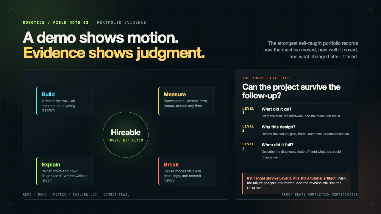
The strongest repositories show logged metrics and a commit history that reflects iterative debugging. They include real-robot deployment and reliability data, not simulation alone. Public LeRobot datasets, contributions to ROS 2, Nav2, MoveIt, Isaac Lab, or LeRobot, and integration projects with clear documentation all carry signal.
Common red flags are equally specific: ROS 1 projects with no migration story; claimed work that collapses under follow-up questions; deep learning without kinematics or embodiment; and certificates weighted far above the contribution they represent.
| README block | Question it answers | Weak substitute |
|---|---|---|
| Video at the top | What actually ran? | A still render or diagram only |
| Architecture or wiring diagram | How do the layers connect? | A dependency list with no data flow |
| Metrics and test setup | How well did it work, and under what conditions? | “Works well” without a denominator |
| What broke and how you fixed it | Can you diagnose your own system? | A tutorial transcript |
| Reproduction steps | Can another person verify the claim? | One giant final commit |
Practice: rewrite the READMEs of your three best projects. Put a video first, show the wiring or architecture, report measured numbers, and include a “What broke and how I fixed it” section. That section is difficult to fake and is often the clearest proof of engineering ability.
Interviews test diagnosis, not LeetCode alone
Expect inverse kinematics, PID and feedback loops, sensor fusion, Kalman filters, SLAM, path planning including RRT, and C++ versus Python trade-offs. Strong teams may provide a MuJoCo or Isaac scene with a deliberately broken controller, ask you to debug a ROS 2 architecture problem scoped to the role, or spend a long time on one past failure.
The source points to Glassdoor's indexed robotics interview questions for examples. More important is a live drill: have someone interrogate your own repository for twenty minutes. Why this gain? Why that sensor? What happens when the battery sags? What did you try first? If you cannot answer three levels deep, the project is not ready for the résumé.
Month 6 build gate
- Collect a demonstration dataset and deploy a policy on your own hardware.
- Distinguish behavior cloning, ACT, diffusion policy, and reinforcement learning.
- Identify which VLA weights are actually open and which hardware constraints apply.
- State the specialty you are pursuing and why your portfolio supports it.
- Publish three projects with video, metrics, reproduction steps, and failure analysis.
- Defend every design choice in one project through three levels of follow-up.
What six months can and cannot promise
The honest boundary is important: this route will not turn a beginner into a senior robotics engineer. Senior work in this field usually means five or more years of deploying real-time systems on physical robots. What six focused months can produce is a person who can build, debug, and explain a working stack from the electrical layer to a learned policy, with enough artifacts to enter the field and continue compounding.
The demand picture, with caveats
The author checked several widely repeated numbers and found a mixed picture as of September 2026. These are source-attributed market observations, not evergreen guarantees:
- Crunchbase is cited for $47.4 billion raised by physical-AI startups in H1 2026 across 521 deals, more than 2022–2024 combined.
- Narrower robotics-only funding is cited at $18.8 billion by late June 2026, versus $15 billion for all of 2025.
- Cited rounds include Neura Robotics at $1.4 billion, Skild AI at $1.4 billion, Apptronik at $520 million, and Figure at a reported $39 billion post-money valuation.
- Hiring lags capital: A3 is cited for 2.0% unit growth in North American robot orders in H1 2026, while IFR is cited for a 9% decline in US installations in 2024.
- BLS occupational projections are described as 1–2% growth, not the unsourced 10% often repeated in career articles.
- BLS is cited for 106,100 annual software-developer openings versus roughly 57,200 for mechanical, electrical, and industrial engineers combined.
- The largest posting category is cited as Automation and Robotics Technician at 20.3% of 3,113 postings, with 68% of technician roles filled by an associate's degree or certificate.
The defensible conclusion is not “everyone will be hired.” It is that capital is arriving faster than qualified specialists, demand is uneven across roles and regions, and entry paths through technician, teleoperation, integration, and data collection may be more open than the narrow title “robotics engineer” suggests.
US salary ranges cited
| Level or role | Range cited | Source context |
|---|---|---|
| Official median | $122,930 | O*NET / BLS robotics engineers |
| Entry level | About $80k–$100k | Payscale and Salary.com; coastal and funded employers may exceed it |
| Mid level, 3–6 years | $120k–$165k | Conventional employers |
| Senior | $160k–$230k | Mainstream range |
| Figure Helix AI Engineer, Robot Learning | $200k–$400k base | Live listing cited by the source |
| Figure perception role | $200k–$350k | Live listing cited by the source |
| Robot foundation-model specialist | $280k–$475k total compensation | Recruiter-reported and heavily equity-weighted |
Outside the US, the source cites roughly €70,000 median total compensation in Germany, CHF 95,000 in Switzerland, £32,000–£50,000 base in the UK, and around ₹653,000 in India. These are not directly comparable because tax, equity, cost of living, seniority, and source methodology differ.
| Contract or entry path | Number cited |
|---|---|
| Upwork robotics engineering | $22–$70/hour, cluster around $30–$50/hour |
| ROS node implementation | $500–$1,200 per deliverable |
| Launch configuration | $1,200–$2,500 |
| Sensor integration pipeline | $4,500–$7,000 |
| Full system architecture | $7,000–$12,000 |
| ZipRecruiter ROS developer average | $52.84/hour |
| Teleoperation and data collection | $28.24/hour average; most citations $22.12–$32.93 |
| Figure Humanoid Robot Operator | $25–$35/hour; no degree requirement stated in the cited listing |
| Robotics technician median | $73,900 |
The source also makes an economically important point about integration: in a robot cell, the robot itself may average only about 25% of total project cost. Engineering, safety, commissioning, and integration account for the rest. A $35,000 arm can become an $80,000 working system. The gap is the service being sold, and it explains why integration skills remain valuable even when hardware becomes cheaper.
The six-month operating rule
Do not try to complete every linked resource. Use the links as a map and select the one or two sources that match the current build. Two focused hours a day are enough when they repeatedly pass through the same loop:
- Build one small physical or simulated behavior.
- Instrument it with logs, measurements, video, or tests.
- Break it deliberately and observe the failure mode.
- Diagnose the lowest layer that can explain the symptom.
- Fix one variable and measure the difference.
- Explain the result in a README another engineer can verify.
By the end, the point is not that you consumed a curriculum. It is that someone can open five repositories and see a line follower responding to control changes, a balancing robot rejecting disturbances, a custom bracket that fits its hardware, a ROS 2 map produced by your own robot model, an arm moving through measured kinematics and planning, and a learned policy with an honest success rate.
That is how six months changes what you can do with your hands and your head. The hardware is cheaper than it has been, the software stack is largely open, and the courses are available. The scarce part is still the discipline to make machines work and the clarity to prove how you know.
Source and attribution: This bilingual edition is adapted and edited from Ronin's X long-form article “How to become a Robotics Engineer in 6 months (RESOURCES)”, published 2 September 2026. The original author's YouTube-channel promotion and promotional image are intentionally omitted. Prices, links, funding figures, job counts, salaries, product availability, and software release dates were reported as of September 2026 and should be rechecked before purchasing or making career decisions.
Source:X Longform / Roninhttps://x.com/DeRonin_/status/2095180126359105955